Starting Methods of Synchronous Motor for LCI:
It has been pointed out that a Starting Methods of Synchronous Motor for LCI, even though complicated in its construction, has an advantage that it can provide the necessary reactive power required by the inverter, except at low speed. Among all the drives possible with synchronous motor, Starting Methods of Synchronous Motor for LCI drive is popular in CLM mode, and is known as converter motor. At low speeds, i.e., speeds below 10% of base speed, commutation should be assisted. Several methods are employed for starting and bringing the motor to a speed where load commutation can take over.
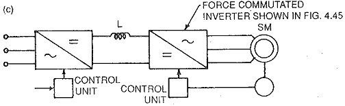
1.Forced commutation can be employed at very low speeds. The commutation circuit can be switched off when the speed is reached at which machine voltages are capable of commutating the inverter. As forced commutation is required only at low speeds, the size of the commutation circuit is relatively small. A CSI using individual commutation is very suitable and is shown in Fig. 4.46(a).
2.Forced commutation at low speeds can be obtained by means of a fourth leg of the inverter containing auxiliary thyristors (Fig. 4.46(b)). A commutating capacitance is connected across the start point and common point of the two At low speeds the voltage of capacitance is used to quench the thyristors. When the motor attains the speed at which machine commutation can take place the fourth leg is cut off. The inverter is called third harmonic commutated inverter.
3.DC Link current interruption can be employed to achieve the operation at low speeds. This is a kind of artificial quenching. The dc link current is interrupted at the instant of commutation and at the same time the line side converter is controlled so that it goes to inversion from rectification. The rotor position sensor sends information to the control unit of the machine side converter to block the firing pulses to the outgoing thyristor and provide them to the incoming one. The dc link voltage has changed its polarity due to transition of line side converter. Consequently the dc link current decays to zero and is maintained at zero value for a time greater than the turn off time of the thyristor. After this dead zone the line side converter is again made a The dc link current builds up and flows through the machine phases via the new thyristor. There is a similar sequence if operations take place in the other commutations.
The interruption of link current to zero at the instant of commutation and its building up to the reference value after commutation are delayed by the link inductance. When the inductance is large and frequency is high the current may not even reach its reference value by the time the next commutation starts. To make the current variation faster, a thyristor is placed across the link inductance. Only machine and line inductance will be effective during variation of current. This thyristor is fired just at the instant when the zero current should exist. At the end of commutation, when the link voltage changes its sign it automatically ceases conduction. The link current flows through the inductance and the new phase via the thyristors.
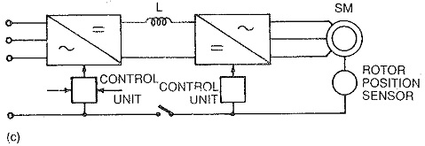
The schematic diagram of connections of this method are shown in Fig. 4.46(c). The line side converter receives its firing pulses from CUI, whereas CU II provides firing pulses to the machine side inverter. The current controller provides reference current. The thyristors T21 and T26 are fired in the inverter. The machine current builds up to the reference value. The rotor stun; to move and after it has moved by the set amount the rotor position sensor sends information to block the firing pulses to T21 and provide them to T22. This is to advance the stator mmf by 60°. At the same time the line side converter starts working as an inverter. The link voltage changes its polarity. The link current is interrupted. The decay of current to zero is made faster by short circuiting the link inductance. The current through the outgoing thyristor is zero and it is maintained for a time greater than turn off time to ensure its forward blocking capability. After this time, the line side converter is changed to rectification. The link voltage polarity changes. The current builds up to reference value. The thyristor across the inductance ceases to conduct. The thyristors T22 and T26 conduct till the next commutation in the sequence starts, i.e., after a definite interval when the rotor has moved by 60°, T24 is fired and a similar process takes place to commutate T26 to T24.
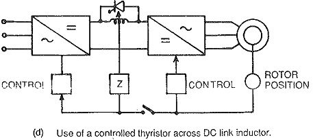
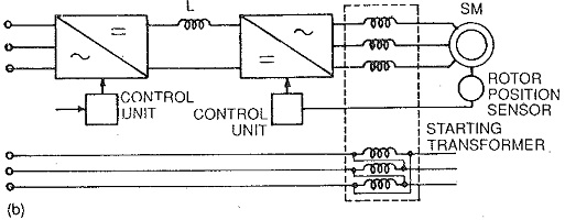
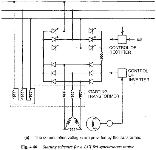
4.Use of an additional transformer: A method suggested by E. Kubler, making use of an additional inductive ac voltage for commutation of current from one thyristor to the other can be used. The details are given in Fig. 4.46(d). The process is explained assuming that the thyristors T21 and T26 conduct to start with. When the rotor rotates by the desired angle the pulse to T21 is removed and the thyristor T22 is fired. When there is no induced voltage, the current divides between T21 and T22. This induced voltage is introduced by means of a transformer. A voltage is induced in the current carrying winding of the auxiliary transformer. This voltage is short-circuited due to the conduction of T21 and T22 and acts as a commutation voltage. This decreases the current to zero in T21 and increases current to dc link value in T22. The thyristor T21 is quenched and the current commutates over to T22.
In the next commutation the thyristor T24 in the other half of the bridge is fired and T26 is commutated to T24. In this way in a sequence commutations take place to accelerate the rotor. When the desired speed is reached the machine commutation takes place. The primary of the transformer is disconnected from the line and secondary is short-circuited.
For satisfactory commutation the machine frequency must be smaller than the transformer frequency. This condition is satisfied because the commutation assistance is required up to 10% of rated frequency. The rating of transformer need be only 10% of machine rating.
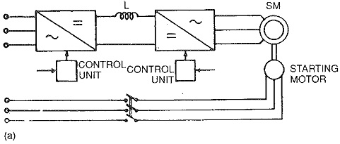
5.Sometimes when the power is small an auxiliary motor can be used to run up the Starting Methods of Synchronous Motor for LCI to the desired speed.
Among the methods discussed above the methods using forced commutation are universally applicable ones. They are suitable for high speed motors having high starting torque. They make use of the current handling capacity of inverter thyristors and provide symmetrical currents during starting.
The other methods can be employed when these qualities are not of very much significance.