Voltage Source Inverter Fed Synchronous Motor Drive:
An inverter fed synchronous motor has been very popular as a converter motor in which the synchronous motor is fed from a CSI having load commutation. Of late more attention is being paid towards understanding the behaviour of synchronous motors fed from a Voltage Source Inverter. These drives can also be developed to have self control, using a rotor position sensor or phase control methods. It has been reported in the literature that these drives might impose fewer problems both on machine as well as on the system design. A normal VS1 with 180° conduction of thyristors requires forced commutation and load commutation is not possible.
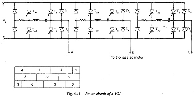
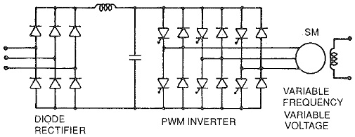
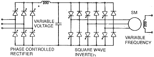
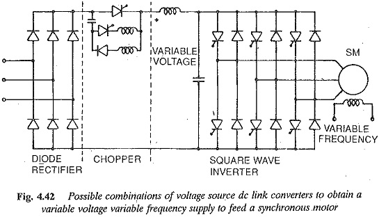
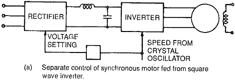
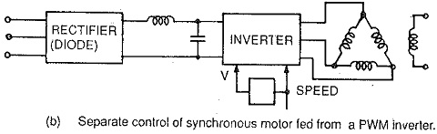
A typical power circuit of a voltage source inverter is shown in Fig. 4.41. Three combinations are possible, to provide a variable voltage variable frequency supply to a synchronous motor (Fig. 4.42). The voltage control can be obtained external to the inverter using a phase controlled rectifier. The link voltage is variable. This has the disadvantage that commutation is difficult at very low speeds. As the output voltage is a square wave the inverter is called variable voltage inverter or square wave inverter. The second alternative is to have voltage control in the inverter itself, using principles of PWM or PSM. The inverter is fed from a constant link voltage. A diode rectifier would be sufficient on the line side. This does not have difficulties of commutation at low speeds. Very low speeds up to zero can be obtained. The third alternative is to interpose a dc chopper in between the rectifier and the inverter. The system may appear cumbersome at first sight, but it has advantages. Three simple converters are used to give the desired result. It is possible to reduce the size of link inductance by having a synchronous control of the chopper.
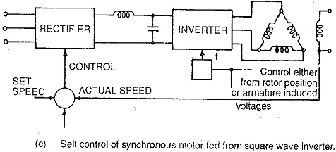
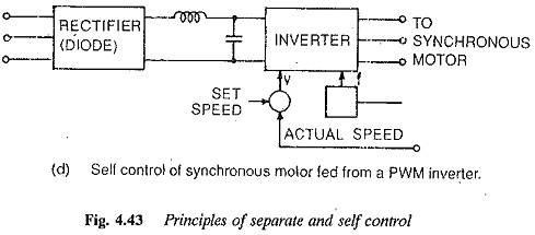
A voltage source inverter feeding a synchronous motor can have either separate control or self control. In the former the speed of the motor is determined by external frequency from a crystal oscillator. Open loop control is possible. The motor has instability problems and hunting, similar to a conventional motor. In the latter the inverter is controlled by means of firing pulses obtained from a rotor position sensor or induced voltage sensor. The motor is in the CLM mode and has better stability characteristic (Fig. 4.43).
The output voltage of the inverter is non-sinusoidal. The behaviour of the motor supplied from the inverter is entirely different from the behaviour of the motor operating on a conventional sinusoidal supply. A knowledge of the behaviour is essential. The steady-state performance enables one to have a proper choice of the thyristors, and also to determine the effects of non-sinusoidal waveforms on torque developed and machine losses.
The stator current drawn by the motor when fed from the square wave inverter has sharp peaks and is rich in harmonic content. These harmonics can cause additional losses and heating of the motor. They also cause pulsating torques which are objectionable at low speeds. Thus the performance with respect to additional heating due to harmonics, and pulsating torques is similar to that of an induction motor.
When a PWM inverter is used, these harmonic effects are reduced. The stator currents are less peaky and have reduced harmonic content. Accordingly additional losses due to harmonics, consequent motor heating and torque pulsations are decreased. These effects become minimal.
The discussion on regeneration given for induction motors holds good for these cases also. With the square wave inverter another phase controlled rectifier is required on the line side. Dynamic braking can be employed. When a PWM inverter is used, two cases may arise. The inverter may be fed from a constant dc source in which case regeneration is straight forward. The dc supply to the inverter may be obtained from a diode rectifier. In this case an additional phase controlled converter is required on the line side.
A square wave inverter drive must have a phase controlled converter on the line side. Due to phase control the line power factor is very poor. A diode rectifier is sufficient in the case of PWM inverter. The line pl. improves to unity. In either case the machine p.f. can be improved by field control. With a view to minimizing the inverter size as well as losses in the inverter and motor, it is advantageous to operate the motor at UPF.
A VSI drive provides reasonably good efficiency. Converter cost is high and inultimotor operation is possible. Open loop (separate) control may pose stability problems at low speeds. CLM mode is very stable. PWM drive has a better dynamic response than a square wave drive. This finds application as a general purpose industrial drive for low and medium powers.