Voltage Control Techniques for Inverters:
It has already been mentioned that Inverter Control providing a variable frequency supply to three phase motors should be capable of providing a variable voltage. This is required to avoid saturation and ensure operation at constant flux density. The Voltage Control Techniques for Inverters can be affected either external to the Inverter Control or within it.
The Voltage Control Techniques for Inverters can be done in two ways.
- by varying the dc link voltage
- by varying the ac voltage at the output using a variable ratio transformer
(a) The variation of dc link voltage can be achieved in many ways. It has the advantage that the output voltage waveform is maintained over a wide range of frequencies. But at very low frequencies, the dc link voltage may be too low to commutate the inverter. This limits the lowest operating frequency and hence the frequency range. The dynamic response is also poor.
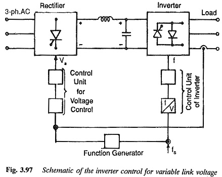
A variable dc supply can be obtained by using a phase controlled rectifier on the line side. A closed loop control varies the firing angle depending upon the frequency. The function generator (Fig. 3.97) gives a relation between the stator frequency and applied voltage to the stator for constant air gap flux or given flux conditions in the motor. The output of the function generator is voltage for a given value of fs. This voltage is compared with the measured value of voltage and the error so obtained is used to change the firing angle of the converter on the line side. The frequency is obtained by controlling the firing and conduction of the thyristors of the machine side converter. A current loop is also employed to limit the current to safe values during dynamic operation of the system.
A combination of a diode rectifier and a dc chopper is used for varying the dc link voltage. Closed loop control in this case changes the time ratio of the chopper. Yet another way is to use a variable ratio transformer which operates at constant frequency, before the diode rectifier. These methods are shown in Fig. 3.97.
(b) The Voltage Control Techniques for Inverters Control can be affected by means of a variable ratio transformer interposed between the motor and inverter. The method is very simple. Even in this case the waveforms of output voltage remain the same over a wide frequency range. The line side converter can be a simple diode rectifier. This provides a good pf. The main disadvantage of this method is that the transformer has to be designed for low frequencies and its size is large. The system also has an extremely poor dynamic response.
Voltage control within the Inverter:
The dc link voltage is constant and the inverter is controlled to provide-both variable voltage and variable frequency. As the link voltage is Constant a simple diode rectifier may be employed on the line side. Variable voltage variable frequency supply to the motor is obtained within the Inverter Control itself using suitable control based on the principles of PWM or PSM (phase shift modulation).
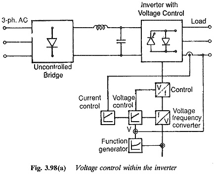
The block diagram of control of the constant voltage inverter is shown in Fig. 3.98(a). The voltage is sensed and compared with the output of the function generator. The error is used to change the amplitude of the reference wave in order to obtain the desired value of voltage. The frequency of the reference wave is changed in order to get the desired frequency. As the inverter is supplied at constant voltage commutation problem at low frequencies disappears. The operating frequency extends to zero and the system has a very good dynamic response. The voltage waveform is not the same at all frequencies. At low frequencies the harmonic content may increase.
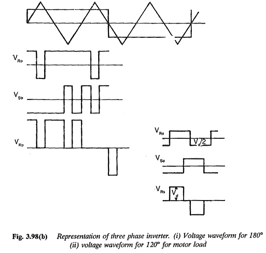
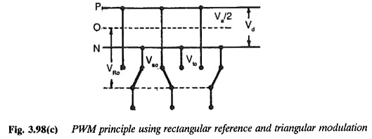
PWM techniques are very widely used. They sometimes provide harmonic elimination also. For this purpose, sinusoidal modulation is used. The principles of PWM are illustrated in Fig. 3.98.
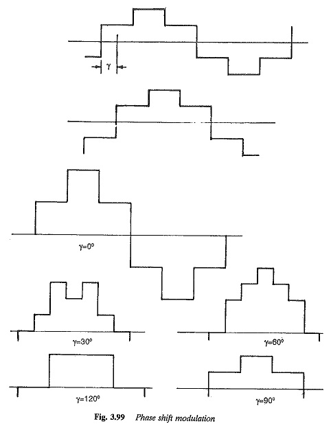
The PSM technique for Voltage Control Techniques for Inverters is illustrated in Fig. 3.99. This method has some disadvantages. The voltage waveform has a high harmonic content at lower frequencies and the utilization of the thyristors is very poor. The technique involves two inverters, making it costly for low power applications.