Features of Variable Voltage Inverters:
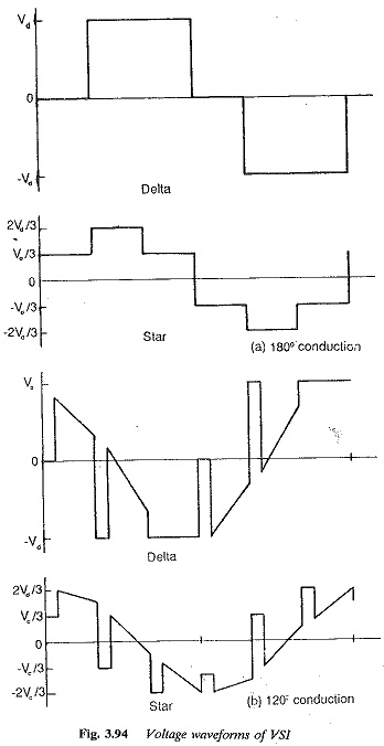
The inverter has an impressed dc voltage. The output voltage of the inverter is decided by the firing and duration of the thyristors. The conduction of the thyristors can be either 180° or 120°, depending upon the control employed. In the case of 180° conduction three thyristors conduct at any instant, two in one half and the third in the other half. The motor phase voltage can be determined from the known potentials of the output terminals. The output voltage is in the form of a square or stepped wave and is independent of load. In case of 120° conduction only two thyristors conduct at any instant, one in the top half and the other in the bottom half. The control is simple compared to the 180° case, but the output voltage is dependent on the load. The Variable Voltage wave forms of these inverters are shown in Fig. 3.94. Due to the extensive use the 180° of the 180° case, a variable voltage inverter is also called a square wave inverter.
At very low speeds there are commutation problems, as the input voltage may not be sufficient for commutating the thyristors. This imposes a lower limit on the frequency.
A multimotor drive is possible using this type of inverter. The commutation is load independent, and the converter and load need not be matched. The converter represents a source and the motor can be plugged on.
Output frequencies up to 1500 Hz are possible using this converter which makes it very suitable for high speeds. Transistorised converters of rating 10 KVA are available up to 6000 Hi
The converters are built upto a rating of 200 KVA. Due to commutation problems at low speeds, the lowest operating frequency is 10 Hz. The speed control range is 1 : 20. The inverter is not suitable for acceleration of the motor on load and for sudden load changes. The dynamic behaviour is poor at low speeds and good at high speeds.
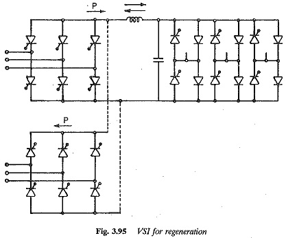
Regeneration requires an additional phase controlled converter at the line terminals, as shown in Fig. 3.95. – The output voltage has harmonic components which depend on the load. The load current is non-sinusoidal. When an induction motor is fed from this type of inverter the harmonic content of the motor current is decided by the motor leakage reactance. The leakage reactance also influences the peak current, which in turn influences the choice of the inverter thyristors. The higher the leakage reactance, the smaller is the harmonic content and the peak value of the motor current. Both the harmonic losses and the torque pulsations are influenced by the leakage reactance. Open loop control is possible but there may be stability problems at low speeds. The line power factor is poor due to phase control.
Inverters with constant link voltage
In the case of these inverters, the voltage impressed is constant and voltage control is obtained in the inverter itself using the principle of PWM. The principle is illustrated in Fig. 3.93, with the resulting voltages shown.
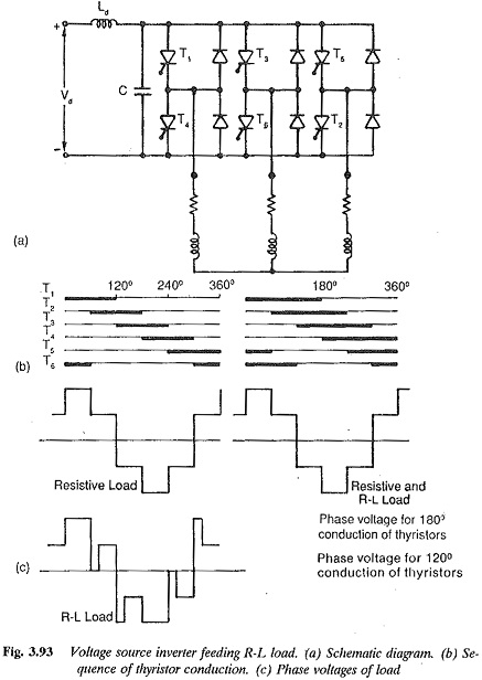
The problem of commutation at low speeds is avoided , which makes it possible to extend the speed control up to zero speed. The Variable Voltage waveform is not a square wave-but is pulsed, depending upon the type of modulation employed. The inverter has a very good dynamic response.
The specific features of this type of inverter can be summarised as follows:
1. It has a constant dc link voltage and uses the PWM principle for voltage control.
2. The output voltage waveform is improved with respect to the harmonic content, which is reduced. Therefore torque pulsations are not a problem, even at low speeds.
3.The parallel operation of many inverters on the same bus system is possible.
4. Uninterrupted operation using a buffer battery is possible for long periods.
5. When a diode rectifier is used the power factor on the ac side is excellent.
6. The power and control circuits are complicated, when compared to square wave inverters.
7. Four quadrant operation is possible. During braking a battery or another converter with phase control is used on the line side.
8. Both single and multimotor operations are possible. Speed reversal is very smooth and it can be achieved-with full torque capability of the motor. The dynamic behaviour is fast.
9. Inverters are built up to 150 Hz and a rating of 450 kVA. The speed range is 1 : ∞
10. The inverter and load need not be matched. The inverter can be considered as a source and the load plugged on.
11. The harmonic content of the load current is further reduced by the load inductance; by leakage reactance in the case of a motor load. The peak current capability of the inverter can be smaller than that of square wave inverters, which decreases further if the leakage reactance is large. The filter size can be smaller than that of square wave inverters.
12. Open loop operation is possible. The inverter has a fast response and very good dynamic behaviour.