Principle of Operation of Induction Motor:
The Principle of Operation of Induction Motor in Figure 9.4 shows the cross-sectional view of an induction motor. The stator is fed from a 3-phase supply of voltage V/phase and frequency f Hz. The rotor is wound 3-phase for as many poles as the stator and is short-circuited. It is assumed that the stator resistance and leakage reactance are both negligible so that
![]()
where
- E1 = stator induced emf/phase
- kw1 = stator winding factor
- Nph1(series) = stator series turns/phase
- Φr = resultant air-gap flux/pole
It is seen from Eq. (9.1) that irrespective of the load conditions existing on the rotor,Φr, the flux/pole established in the air-gap is constant, related to the applied voltage in view of the assumption made.
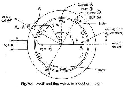
The mmf vector F̅r with associated flux density vector B̅r which is responsible for production of Φr rotates at synchronous speed as it is associated with balanced 3-phase currents drawn by the stator. The relative speed between B̅r and the rotor causes induction of a current pattern in the shorted rotor. The torque produced by interaction of B̅r and the rotor currents would by Lenz’s law tend to move the rotor in the direction of rotation of B̅r so as to reduce the relative speed. The motor is thus self-starting and the rotor acquires a steady speed n < ns depending upon the shaft load. It may be noted that no torque is produced at n = ns because the relative speed between B̅r and rotor being zero, no currents are induced in the rotor.
Figure 9.4 shows the relative location of vectors F̅r, B̅r(air-gap mmf and flux density),F̅2 (rotor mmf) wherein F̅r leads F̅2 by angle δ = 90°+ θ2 (motoring action), θ2 is the angle by which rotor currents lag rotor emfs. The angle θ2 however, is very small as rotor reactance is far smaller than rotor resistance. The stator mmf vector is then given by
![]()
is located on the vector diagram. At the instant at which the diagram is drawn, the stator and rotor phase a (shown as single coil) currents are maximum possible. The reader may verify the location of vectors from the phase a currents applying the right hand rule.
Slip and Frequency of Rotor Currents:
With reference to Fig. 9.4, it is easily observed that B̅r moves at speed (ns – n) with respect to rotor conductors (in the direction of B̅r). This is known as slip speed. The slip is defined as
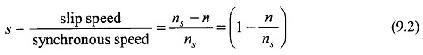
Obviously s = 1 for n= 0, i.e. for the stationary rotor and s = 0 for n = ns, i.e. for the rotor running at synchronous speed.
The frequency of currents induced in the rotor is
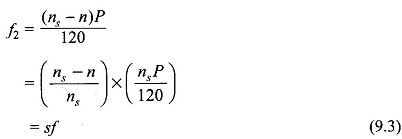
The normal full-load slip of the Principle of Operation of Induction Motor is of the order of 2%-8%, so that the frequency of the rotor currents is as low as 1-4 Hz.
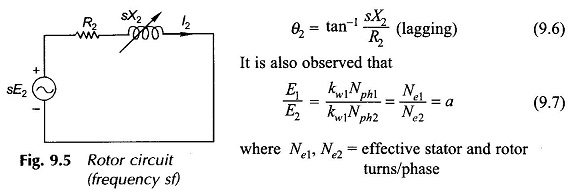
The per phase rotor emf at s = 1 (standstill rotor) is given by
![]()
At any slip s, the rotor frequency being sf, the rotor induced emf changes to sE2. Consider now the impedance of the rotor circuit
![]()
where
- X2 = leakage reactance of rotor at standstill (rotor frequency = stator frequency, f)
When the rotor runs at slip s, its frequency being sf, its impedance changes to
![]()
It is, therefore, seen that the frequency of rotor currents, its induced emf and reactance all vary in direct proportion to the slip. Figure 9.5 shows the rotor circuit at slip s. The phase angle of the circuit is
Rotor MMF and Torque Production:
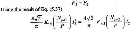
In Fig. 9.4 as the resultant flux density vector B̅r rotates at speed (ns — n) with respect to rotor, maximum positive emf is induced in the rotor coil aa’ (indicated by dot in conductor a and cross in conductor a’) when B̅r lies 90° ahead of the axis of the coil. Since the current in the rotor lags the emf by θ2, the current in coil aa’ will be maximum positive when B̅r has moved further ahead by angle θ2. It is at this instant of time that the rotor mmf vector F̅2 will will lie along the axis of coil aa’. It is, therefore, seen that B̅r (or F̅r) lies at an angle δ = (90 + θ2) ahead of F̅2. Further, F̅2 caused by the rotor currents of frequency f2 = sf rotates with respect to the rotor conductor at speed (ns — n) and at speed ns. with respect to the stator as the rotor itself is moving in the same direction at speed n with respect to the stator. Thus F̅r and F̅2 both move at synchronous speed ns with respect to the stator and are stationary relative to each other with F̅r lying ahead of F̅2 by angle (90° + θ2). The interaction of the rotor field and the resultant field creates a torque in the direction of rotation of F̅r.
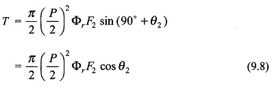
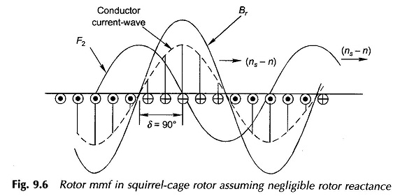
Consider now the case of the squirrel-cage rotor with conductors spread uniformly around the rotor periphery. The rotor reaction mmf F2 is better visualized from the developed diagram of Fig. 9.6 wherein the rotor is imagined to be stationary and the Br – wave moving with respect to it at slip speed (ns — n). Let the rotor reactance be considered negligible so that the conductor (shorted) currents are in-phase with the conductor emf s. The conductor current pattern is, therefore, sinusoidally distributed and is in space phase with Br-wave and moves synchronously with it. The rotor mmf-wave is a stepped-sinusoidal with the same number of poles as the Br-wave moving synchronously with it. Its fundamental (F2) shown in Fig. 9.6 lags Br-wave by 90°. If the rotor reactance is now brought into picture, the conductor current-wave and, therefore, the rotor mmf-wave would lag behind by angle θ2. Thus the angle between the Br-wave and F2-wave would be (90° + θ2), the same as in the wound rotor. A squirrel-cage rotor, therefore, inductively reacts in the same way as a wound rotor except that the number of phases is not obvious — one can consider it to have as many phases as bars/pole. A squirrel-cage rotor can always be replaced by an equivalent wound rotor with three phases.
It is seen from Eq. (9.8) that a low-reactance rotor (low θ2 = tan-1 jsX2/R2) will generate a larger torque for given Φr,F2 and s. A squirrel-cage motor is superior in this respect as compared to a wound-rotor motor as the cage rotor has lower reactance since it does not have winding overhang.
One very important observation that can be made in Principle of Operation of Induction Motor here is that while the rotor currents have a frequency sf, the mmf (F2) caused by them runs at synchronous speed with respect to the stator. In other words, the reaction of rotor currents corresponds to the stator frequency (f) currents flowing on an equivalent stationary cylindrical structure placed inside the stator in place of the rotor. Or, to put in another way, the rotor currents as seen from the stator have frequency f but have the same rms value.
The stator mmf vector F̅1 is located on Fig. 9.4 from the vector equation
![]()
Further, F̅1 can be divided into components as
![]()
where F̅2 is in opposition to F̅2 and equal in magnitude and
![]()
The stator current which causes F̅1 can, corresponding to vector Eq. (9.10), be divided into components
![]()
Here I̅m can be recognized as file magnetizing current which causes the resultant mmf Fr and the resultant flux/pole, Φr, while I′2 is that component of the stator current which balances the reaction F2 of the rotor current I2.
Figure 9.4 also shows the relative location of stator coil AA’ and the positive direction of current in it. This instantaneous vector picture holds when I2 has maximum positive value. For F′2 to cancel F2, the stator current component which balances the rotor mmf must be in phase with the rotor current as seen from the stator.
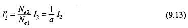
In terms of magnitudes F′2 is oppositely directed to F2, for them to cancel out while I′2 and I2 must obey the proportionality of Eq. (9.13) and must be in phase.
Further, by reference to Fig. 9.4, it can easily be seen that in the stator the positive direction of emf E1 opposes the positive direction of I1, while in the rotor the positive direction of I2 is in the positive direction of sE2. This is analogous to the transformer case.
With the direction of positive current in the stator coil AA’ marked as in Fig. 9.4 and the direction of the coil axis indicated, the law of induction which will give positive emf in opposition to current is
![]()
This Principle of Operation of Induction Motor has the same sign as used in the transformer case so that the flux phasor Φr and magnetizing current which creates it lags E1 by 90°. In the circuit model Im would therefore be drawn by the magnetizing reactance Xm across E1.