Single Phase Induction Motors Working Principle:
Single Phase Induction Motors Working Principle are inferior in performance and lager in weight and volume compared to three-phase motors of the same rating. However, they are simple, robust, reliable and less expensive for small ratings. They are employed in low power drives in small industries and domestic and commercial applications, where only single-phase supply is available. They are generally available up-to 1 kW rating. Applications are many such as compressors in refrigerator and air-conditioners, washing machines, dryers, fans, pumps, domestic appliances, small machine tools, printing machines, tape recorders.
A Single Phase Induction Motors Working Principle has a cage rotor and a single phase winding in the stator. The pulsating magneto motive force (mmf) produced by ac current in stator winding can be considered to be equivalent to two constant amplitude mmf waves revolving in opposite directions at synchronous speed. Each of these revolving mmf wave induces its own rotor current and produces induction motor action just as in a 3-phase motor.
Fig. 6.60 shown torques produced by the two revolving fields and also net torque produced by the motor. When the rotor is stationary, it reacts equally to both waves, and no torque is developed. Therefore, a Single Phase induction motor with single stator winding inherently has no starting torque. But if started by auxiliary means, it will develop torque and continue to run. When the rotor is running, induced rotor currents are such that their mmf opposes the reverse stator mmf to a greater extent than they oppose the forward stator mmf. Result is that the forward flux wave, which develops forward torque is bigger than the reverse flux wave which develops reverse torque. Net torque (difference between the forward and reverse torques) produced maintains the motion. As the speed increases, forward torque increases and reverse torque decreases. Therefore, net torque progressively increases with speed. When started from its zero speed, first it builds up slowly but later accelerates fast to a speed near synchronous. Backward rotating field increases the full load slip and therefore reduces efficiency and power factor. Interactions between forward rotating field and rotor currents induced due to reverse rotating field, and reverse rotating field and rotor currents induced due to forward rotating field produce second harmonic torque pulsations which cause vibrations and noise.
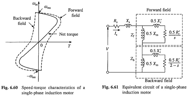
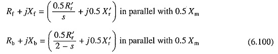
Figure 6.61 shows equivalent circuit of a Single Phase Induction Motors Working Principle with single winding. Rotor equivalent circuits accounting for the forward and backward rotating fields are indicated in the figure. When rotor moves in forward direction with a slip s (with respect to forward rotating field) then the slip sn (with respect to backward field) will be
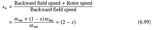
Hence for backward field the rotor resistance has been divided by (2 — s) in the equivalent circuit from which stator current Is can be computed for any assumed value of slip when the motor impedance and applied voltage are known.
Let
Power transferred to the rotor (or air-gap power) due to forward field
![]()
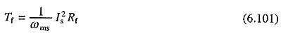
Torque due to forward field
Power transferred to the rotor (or air-gap power) due to backward field
![]()
Torque due to backward field
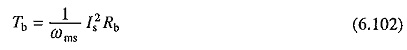
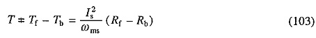
Torque of the backward field is in opposite direction to that of forward field. Therefore, net developed torque