Electrical Braking of Polyphase Induction Motors:
Electrical Braking of Polyphase Induction Motors which consists of different types, namely,
- Plugging (or Counter-Current Braking)
- Dynamic (or Rheostatic) Braking
- Regenerative Braking
1. Plugging (or Counter-Current Braking)
Plugging can be achieved in an induction motor merely by reversing two of the three phases which causes a reversal of the direction of the rotating magnetic field. At the instant of switching the motor to the plugging position the motor runs in the opposite direction to that of the field and the relative speed is approximately twice [(2 – s) times] of synchronous speed i.e., the slip is very nearly equal to two, being equal to (2 – s). So voltage induced in the rotor will be twice of normally induced voltage at standstill and the winding must be provided with the additional insulation to withstand this much voltage.
During plugging period, the motor acts as a brake and it absorbs kinetic energy from the still revolving load causing its speed to fall. The associated power Pmech is dissipated as heat in the motor. At the same time, the rotor also continues to draw power from the stator which is also dissipated as heat. Due to increased rotor frequency there are additional iron losses in the rotor. Thus the heat developed in the rotor during braking period are about three times the heat developed during starting period (or under blocked condition of rotor).
The size of the induction motor where plugging is to be applied, is therefore, decided not by loading conditions alone but by braking condition also.
In case of a squirrel cage motor, energy is dissipated wholly within the machine; whereas in case of wound rotor motor this energy is dissipated also in the external resistance added in the rotor circuit for this purpose.
The conditions for electrical braking of polyphase induction motors can be studied by considering the torque-slip curves of the motor when extended beyond the point of 100 % slip, as shown in Fig. 1.103(a). The ordinate at the point B represents the torque at the instant of plugging and we can see that the torque increases gradually as the motor approaches the standstill, after which, of course, if the supply line is not disconnected it will start up again in the reverse direction in accordance with the ordinary torque-speed curves from A to O. Thus we see that for bringing the motor to rest, it is essential to disconnect the supply to the motor at zero speed.
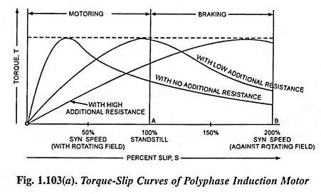
From the torque-slip curves shown in Fig. 1.103 (a), it is observed that magnitude of the braking torque is very much low as compared to the maximum torque exerted by the motor. This is specially so for low rotor resistances. As more and more resistance is inserted in the rotor circuit, maximum torque occurs at increasing values of the slip. This is the reason that squirrel cage induction motors, which are primarily designed for maximum efficiency and, therefore, for low resistance are not much suitable for such type of braking. In case of wound rotor motors, addition of resistance in the rotor circuit gives rise to more and more braking torque and, therefore, wound rotor motors are more suitable for plugging. If the change in rotor resistance is so adjusted that maximum braking torque is exerted throughout, optimum braking will be achieved in minimum
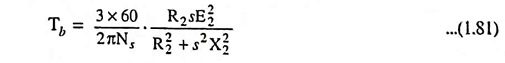
The expression for the braking torque neglecting stator impedance and magnetizing reactance, can be deduced, and is given as
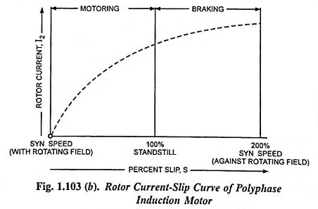
The rotor current can be determined during the braking period from the following relation and is plotted, as shown in Fig. 1.103 (b).

where
- E2 is the emf induced in each phase of the rotor at standstill,
- R2 is the rotor resistance per phase and
- X2 is the rotor standstill reactance per phase and
- s is the slip.
During plugging period, since the induced emf in the rotor is very high, as already stated above, so the rotor current and thereby stator current are very high. However, braking current can be reduced by inserting external resistance in the rotor circuit. From this point also, the wound rotor motors are beneficial as compared to squirrel cage rotor motors.
Cage motors of about 20 kW output are plugged directly, using the star connection if a star-delta switch is provided. Larger motors need stator resistors. Wound rotor motors employ rotor resistors for current limitation as well as developing higher braking torques. Problems of thermal rating may arise for frequent braking duty, as already explained above, and contactors may need frequent servicing.
Simultaneous reversal of stator connections and inclusion of rotor resistance in the wound rotor motors is quite practicable, but the same effect can be achieved by including saturistors in the rotor windings. Alternatively a deep bar rotor cage may give rise in effective rotor resistance following the plugging operation as the slip frequency is suddenly increased from sf to (2 – s) f where f is the supply frequency.
In practice, for reversing drives where braking and starting up of induction motor in reverse direction comprises stages of the same continuous process, plugging is advantageously employed.
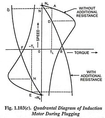
The plugging operation can also be explained with the help of quadrantal diagram shown in Fig. 1.103 (c). Speed-torque characteristics shown in Fig. 1.103 (c) are actually extension of the motor characteristics in the second and fourth quadrant. The explanation of Fig. 1.103 (c) is exactly identical to one for Fig. 1.94 (a) or 1.94 (b).
2. Dynamic (or Rheostatic) Braking
In this electrical braking of polyphase induction motors, the rheostatic braking can be obtained by disconnecting the stator winding from the ac supply and exciting it from a dc source to produce a stationary dc field. In rheostatic braking, the stator winding is employed as a dc field winding and the rotor winding as an armature winding. With a wound rotor machine, external resistors can be inserted into the rotor circuit to provide a load. With squirrel cage machines, however, the rotor winding itself has to form the load.
The source of excitation may be provided either by an independent dc source or from the ac mains through a transformer rectifier set, as shown in Fig. 1.105.
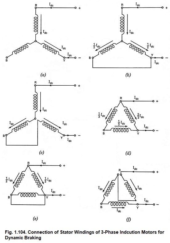
Various methods of connecting the stator winding to a dc source are shown in Fig. 1.104. Though connections shown in Figs. 1.104 (c) and 1.104 (f) give uniform current loading of all the three phases but are complicated in switching operation. Being more simple in this respect, the connections shown in Figs. 1.104. (a) and (b) are usually employed.
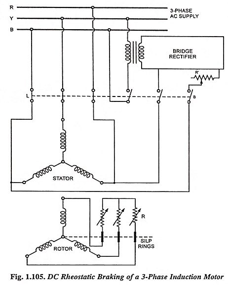
A typical connection diagram is given in Fig. 1.105; the machine operates as a motor with contactors L closed, while with L open and B closed a direct current is supplied through two stator phases, the third being left open circuited. The resistance R’ is inserted in the stator circuit to limit its current. In case of wound rotor motors additional resistance R is inserted in the rotor circuit to control the braking effect.
While the machine is operating normally as a motor, its stator magnetic field is rotating at a synchronous speed in the same direction as that of the rotor, but slightly faster than the rotor conductors. When the stator windings are disconnected from the ac supply and excited with dc, the magnetic field produced will be stationary in space, thus making the rotor conductors move past the field with a speed (1 – s)Ns or SNs. The currents induced in the rotor conductors will be opposite in direction to that corresponding to motoring operation, producing a braking torque.
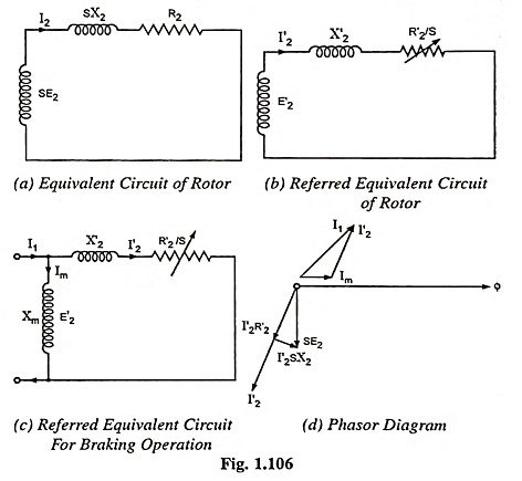
Although the air-gap flux is stationary, there will be the same number of poles as when the machine is excited with ac and the rotor currents will, therefore, have a frequency which is near to the frequency corresponding to synchronous speed (i.e., Ns) initially, but which decreases with rotor speed and becomes zero at standstill i.e., rotor current frequency can be expressed as Sf, where f is the frequency of ac supply. Likewise, the emf induced in the rotor decreases from a maximum when the rotor is running, to zero at standstill. In other words, the emf induced in the rotor will be given by SE2 where E2 is the magnitude of the emf induced in the rotor when it rotates past the field at speed Ns. It is, thus seen that the conditions in rotor during dc rheostatic braking with the speed falling from synchronous to standstill are very much the same as when the motor accelerates in the normal manner. Hence the equivalent circuit of the rotor can be represented as shown in Fig. 1.106 (a). Dividing the voltage and the impedance by S, we have the circuit shown in Fig. 1.106 (b) carrying the same current I2.
Since the stator winding carries only direct current, the inductance of the stator has no effect under steady-state operation. The dc voltage applied across the stator winding is fixed only by the stator winding resistance. There will be no iron loss in the stator core. But the rotor core loss will be of considerable magnitude and hence the rotor resistance value referred to stator, which determines the torque developed during braking, must be corrected to take this into account, The emf induced in the rotor, at synchronous speed, E′2 will be given by ImXm where Im represents the magnetizing current passing through the magnetizing reactance. The circuit shown in Fig. 1.106 (b) can be modified into a circuit shown in Fig. 1.106 (c). The phasor diagram corresponding to this modified circuit is shown in Fig. 1.106 (d),
It may be noted that the rotor current is alternating in nature although it is produced by a constant flux, caused by a magnetizing mmf ImN1, which remains stationary in space. However, when viewed from the rotor, both the magnetizing mmf and the resultant flux in the stator will appear as alternating. Also, since the rotor ampere-turns I2N2 (= I′2N1) must be balanced by the stator ampere-turns so as to maintain the magnetizing ampere-turns ImN1, the stator ampere-turns I1N1 as seen from the rotor, represents the phasor sum of ImN1 and I′2N1.
The effective alternating current I1 depends on the magnitude of direct current carried by the stator and the nature of the stator winding connections, as explained above.
From above discussion, it can be concluded that the operation of the motor during dc rheostatic braking can be analysed by using the equivalent circuit (the type of which we are already familiar) shown in Fig. 1.106 (c).
The braking torque can be determined from the relation
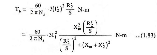
The above equation enables us to determine the braking torque at any speed of a given induction motor, when excited by direct current, I1 corresponding to an equivalent ac, which would have produced the same mmf as that by the actual direct current carried by the stator windings.
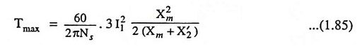
Differentiating Eq. (1.83) w.r.t. S and equating it to zero for a maximum we have slip corresponding to maximum braking torque
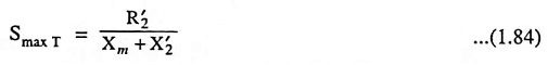
and maximum torque,
Typical performance characteristics of an induction motor are illustrated in Fig. 1.107. The magnitude of the braking torque developed by the motor depends upon the excitation (strength of the field developed by the stator winding), the rotor circuit resistance, and the speed of the motor. Effect of variation of excitation I1 and rotor resistance R2 are also illustrated in Fig. 1.107 (a). For design purposes, the torque-rotor resistance curves illustrated in Fig. 1.107 (b) are sometimes used. With the increase in rotor resistance R2, the speed at which maximum braking torque occurs also increases. But, the maximum torque would not increase in proportion to the square of current (I21), as pointed out by Eq. (1.85), because magnetising reactance Xm decreases due to saturation caused by increase in current I1.
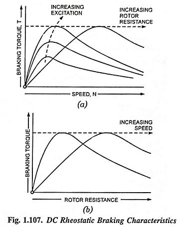
Stable braking operation is on the steeper portion of torque-speed curve [i.e., on the left hand side of the maximum torque position in Fig. 1.107 (a)]. If inadvertently the speed rises above that at which the torque is a maximum, further rise of speed is caused by a decrease in braking torque, which may lead to a further rise in speed in the case of an overhauling load. At the start of applying braking, therefore, we require high resistance in the rotor circuit, which has to be gradually reduced with decrease in speed. Braking torque can be controlled by any or both of the following methods: (i) By controlling the dc excitation (ii) By varying the rotor resistance.
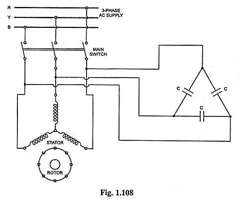
AC dynamic braking may be obtained with self excitation by connecting the stator windings to a bank of static capacitors as shown in Fig. 1.108. In this case the induction machine operates as an induction generator receiving its ac excitation from the static capacitors. The generated electrical energy is dissipated as heat in the rotor circuit. AC dynamic braking is not popular owing to relatively high cost of capacitor banks.
DC dynamic braking takes little power from the supply and provides smooth braking torque, useful for mine winders and high inertia loads. Its advantages over plugging are the absence of the reverse rotation air-gap field [and, therefore, no tendency for the machine to run backwards] and a lower rotor I2R loss. By increasing rotor resistance, the braking torque can be made more effective at higher speeds. This method is, therefore, very much suitable for retarding overhauling loads. In case of a squirrel cage motor, since rotor resistance is small, it will apply braking torque at very low speeds and, therefore, useful only for bringing the load to rest.
The advent of automatic control of dynamic braking in the electrical braking of polyphase induction motors employing closed loop systems, has made the induction motors more popular than dc motors, especially for the drives employing in mine hoists.
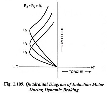
Figure 1.109 shows the quadrantal characteristics of induction motor under dynamic braking condition.
3. Regenerative Braking
Regenerative braking is an inherent characteristic of an induction motor, since it operates as an induction generator when it runs at speed above synchronous and it feeds power back to the supply line.
The 3-phase induction motor can be made to operate at speed above synchronous speed by employing any one of the following processes.
- Switching over to a low frequency supply in frequency controlled induction motors in order to reduce the speed of operation of the drive.
- Downward motion of a loaded hoisting mechanism such as cranes, hoists, excavators etc.
- Switching over to a larger pole number operation from a smaller one in multi-speed squirrel cage motors.
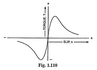
In all the above processes, the slip and torque developed become negative, as shown in Fig. 1.110, and thus the machine acts as a generator, receiving mechanical energy and giving it back to the supply system in the form of electrical energy.
If the load drives the motor above synchronous speed, no switching operation is required. Once the machine is driven above synchronous speed, the braking operation automatically starts. The operating point will depend upon the magnitude of load torque and the nature of torque-speed characteristic of the machine during generating operation. By varying the resistance in the rotor circuit, it is possible to operate at any speed above synchronous speed during braking. In case the driving torque of the load exceeds the maximum braking torque, of which the machine is capable, the system will become unstable and the speed will rise further, probably to a disastrous value, since, the faster the machine runs, the lesser will be the braking torque developed.
In the case of a squirrel cage induction motor, stable speed is obtained at a speed considerably in excess of the synchronous speed and the regenerative braking cannot be applied unless the motor is specially designed to withstand the excessive speed.
Regenerative braking has the disadvantage of the possibility of braking only at super-synchronous speeds and, therefore, is seldome used for braking. This electrical braking of polyphase induction motors method can be used only in hoisting type of mechanism or with a multi-speed squirrel cage motor. It is advantageous on mountain railways too. It returns about 20% of the total energy on certain railway runs and saves a great deal of brake shoe wear.