Braking of Induction Motor Drive:
Following methods are employed for Braking of Induction Motor Drive:
- Regenerative braking
- Plugging or reverse voltage braking
Dynamic (or rheostatic) braking further categorised as:
- ac dynamic braking
- self-excited braking using capacitors
- dc dynamic braking
- zero sequence braking
Regenerative Braking:
The power input to an induction motor is given by
![]()
where Φs is the phase angle between stator phase voltage V and the stator phase current Is. For motoring operation Φs < 90°. If the rotor speed becomes greater than synchronous speed, relative speed between the rotor conductors and air-gap rotating field reverses. This reverses the rotor induced emf, rotor current and component of stator current which balances the rotor ampere turns. Consequently, angle Φs becomes greater than 90° and power flow reverses, giving regenerative braking. Magnetizing current required to produce air-gap flux is obtained from the source. Equations (6.1)-(6.13) are applicable, except that slip is negative. The nature of speed-torque characteristic is shown in Fig. 6.13.
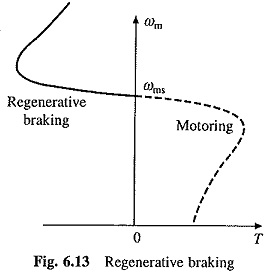
When fed from a source of fixed frequency, regenerative braking is possible only for speeds greater than synchronous speed. With a variable frequency source it can also be obtained for speeds below synchronous speed. When regenerative braking is employed for holding motor-speed against an active load, stable operation is generally possible between synchronous speed and the speed for which braking torque is maximum.
Main advantage of regenerative braking is that generated power is usefully employed and main drawback being that when fed from a constant frequency source, it cannot be employed below synchronous speed.
The utilization (or absorption) of regenerated power occurs in the same way as explained earlier for regenerative braking of dc motors.
Plugging or Reverse Voltage Braking:
When phase sequence of supply of the motor running at a speed is reversed, by interchanging connections of any two phases of stator with respect to supply terminals, operation shifts from motoring to plugging as shown in Fig. 6.14. Plugging characteristics are actually extension of motoring characteristics for negative phase sequence from quadrant III to II. Reversal of phase sequence reverses the direction of rotating field. If the slip for plugging is denoted by sn, then
![]()
Motor performance can be calculated from Eqs. (6.4)-(6.10) when s is replaced by sn or (2 — s). Since at the instant of switchover to plugging, slip can be upto 2, the rotor induced voltage can be twice of its value at zero speed. Consequently, motor current is large, although braking torque is low. In case of wound-rotor motors, a resistance equal to twice the starter resistance is inserted in the rotor to limit braking current to starting value. This also increases braking torque as shown by curve 2 (Fig. 6.14).
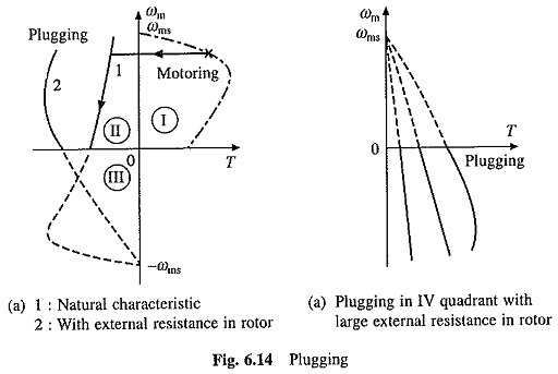
As shown in Fig. 6.14, torque is not zero at zero speed. When used for stopping motor, it is necessary that the motor should be disconnected from supply at or near zero speed. This makes it necessary to use an additional device for detecting zero speed and disconnecting motor from supply. This Braking of Induction Motor Drive is suitable for reversing the motor. As motor is already-connected for operation in reverse direction and torque is not zero at zero or any other speed, motor smoothly decelerates and then accelerates in the reverse direction.
A special case of plugging occurs when an induction motor connected to positive sequence voltages is driven by an active load in the reverse direction (quadrant IV). Crane hoist is one such application. A large rotor resistance is employed so that the characteristics have a negative slope, and thus, drive is steady-state stable (Fig. 6.14(b)).
In this method, mechanical energy supplied to the rotor, either by active load or from kinetic energy stored in motor and load inertia, is converted into electrical energy and wasted in rotor resistance. Additional energy is taken from the source and wasted in rotor resistance. When braked under no load from synchronous speed, total amount of energy dissipated in rotor resistance is given by (3/2)Jω2ms (Eq. (6.63) which is three times the energy stored in inertia. Thus, an additional energy equal to Jω2ms is taken from the source.