Dynamic Braking of Induction Motor(or Rheostatic Braking):
(a) AC Dynamic Braking – AC Dynamic Braking of Induction Motor is obtained when the motor is run on a single phase supply by disconnecting one phase from the source and either leaving it open (Fig. 6.15(b)) or connecting it with another machine phase (Fig. 6.15(c)). The two connections of Figs. 6.15(b) and (c) are, respectively, known as two and three lead connections. When connected to a 1-phase supply, the motor can be considered to be fed by positive and negative sequence three-phase set of voltages. Net torque produced by the machine is sum of torques due to positive and negative sequence voltages. When rotor has a high resistance, the net torque is negative and braking operation is obtained. The motor analysis for two and three lead connections is done as follows:
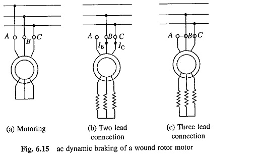
Two Lead Connection: Assume that phase A of a Y-connected motor is open circuited. Then IA = 0 and IC = -IB. Hence positive and negative sequence components Ip and In, respectively, are given by
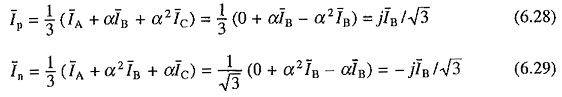
where α is given by Eq. (6.17).
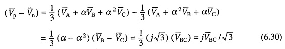
As positive and negative sequence components are equal and opposite, two equivalent circuits can be connected in series opposition. Voltage to be applied to this series combination will be
With an applied voltage jVBC/√3 if current is Ip = – In = jIB/√3, it follows that with an applied phase voltage V the current would be IB/√3. Equivalent circuit may therefore be drawn as shown in Fig. 6.16(a). Although the values of positive and negative sequence components of current are equal, the corresponding torques are not. The nature of speed-torque curves for positive and negative sequence currents, and net torque are shown in Fig. 6.16(b). By suitable choice of rotor resistance, braking torque can be obtained in the entire speed range. As the rotor resistance required is large, ac Dynamic Braking of Induction Motor can only be used in wound-rotor motors.
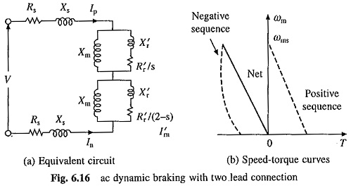
In this connection at high speeds (or at low values of slip), the impedance of positive sequence component part becomes very high. As positive and negative sequence components of current have to be equal, net braking torque is small, and therefore, braking is not very effective.
Three Lead Connection: Here two phases of Y-connected motor winding are connected in parallel in series with the third phase (Fig. 6.15(c)). Let phases A and B be connected together, then
In contrast to two lead connection, here magnitude of positive and negative sequence components of voltage are equal and not the positive and negative sequence components of currents. Equivalent circuit is shown in Fig. 6.17. Positive and negative sequence parts of the circuit are independent, and therefore, there is no restriction imposed on negative sequence component of current by positive sequence part of equivalent circuit. Thus higher braking torques are obtained (compared to two lead connection) at high speeds. The nature of speed-torque characteristic with this connection is same as shown in Fig. 616(b).
Any inequality between the contact resistances in connections of two paralleled phases reduces the braking torque and can even lead to motoring torque, as the condition tends more towards two lead connection with increasing resistance in one of the two phases (as rotor resistance employed is less than the two lead connection). Therefore, two lead connection is generally preferred in spite of its low torque. Main application of single-phase ac braking is in crane hoist.
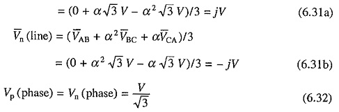
(b) Self-Excited Braking Using Capacitors : In this method three capacitors are kept permanently connected across the motor terminals. Values of capacitors is so chosen that when disconnected from the line, motor works as a self-excited induction generator. Braking connection is shown in Fig. 6.18(a) and self-excitation process is explained in Fig. 6.18(b) for no load condition. Curve A is no load magnetization curve of the machine at a given speed, and line B represents the current through capacitors, given by
![]()
where E is the stator induced voltage per phase.
Capacitors supply the necessary reactive current for excitation. Operation occurs at point C which is the inter-section of two characteristics. When speed falls, value of E for the same magnetization current falls and the new magnetization characteristic a is obtained. On the other hand slope of E vs Ic characteristic increases giving new characteristic b . Intersection of two curves now occurs at c. Thus, reduction in speed while shifts the magnetization curves downward, slope of capacitor voltage vs current curve increases. At certain critical speed, which is usually high, two curves fail to intersect and the machine therefore does not self-excite and braking torque falls to zero. Speed-torque characteristic under self-excited braking is shown in Fig. 6.18(c).
Sometimes external resistors are connected across stator terminals to increase braking torque and to dissipate some generated energy outside the machine. Construction of Fig. 6.18(b) is valid only for no load operation. For more accurate analysis, motor impedance drops should be considered. This scheme is rarely used, as braking torque drops to zero at a speed which is usually high.
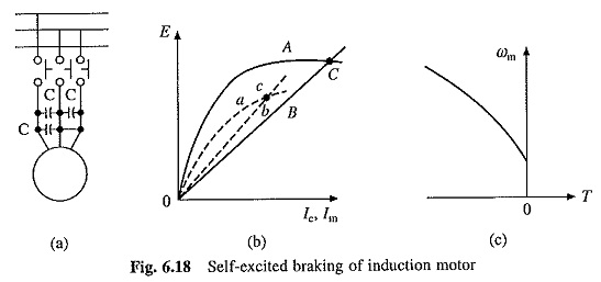
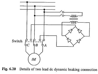
(c) DC Dynamic Braking : It is obtained when the stator of an induction motor running at a speed is connected to a dc supply. Two commonly used connections, two and three lead, for star and delta connected stators are shown in Fig. 6.19. A method of getting dc supply with the help of a diode bridge for two lead connection is shown in Fig. 6.20.
DC current flowing through the stator produces a stationary magnetic field. Motion of rotor in this field induces voltage in the rotor winding. Machine, therefore, works as a generator. Generated energy is dissipated in the rotor circuit resistance, thus giving Dynamic Braking of Induction Motor.
As the field is stationary, relative speed between rotor conductors and the field is now ωm. Frequency of induced voltage will be equal to the frequency of ac source voltage (or rated motor frequency) when ωm = ωms. Let voltage induced in the rotor when running at a synchronous speed be Er. When running at a speed ωm the induced voltage and its frequency will be SEr and Sf, respectively. Then
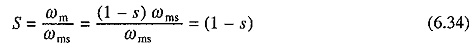
This yields per phase equivalent circuit of Fig. 6.21(a) for the rotor. Dividing all quantities by S will yield an equivalent circuit at the rated frequency. Referring various parameters of equivalent circuit so obtained to stator turns gives per phase equivalent circuit of the rotor shown in Fig. 6.21(b). The equivalent circuit of stator under dc Dynamic Braking of Induction Motor is shown in Fig. 6.21(c). In order to combine with rotor equivalent circuit of Fig. 6.21(b) we should first obtain per phase equivalent circuit of the stator at rated frequency. Equivalent circuit Fig. 6.21(c) suggests that the stator mmf is constant and independent of speed. We, therefore, imagine stator to be fed by a three-phase balanced current source of rated frequency giving a phase current Is. The ac current Is will be equivalent to Id provided it produces stator mmf of same amplitude as the dc current Id. Thus, we are replacing a stationary stator mmf produced by dc current Id by a mmf (produced by Is) of identical amplitude but revolving at synchronous speed. Difference of these two mmfs will be air-gap mmf which will be responsible for producing air-gap flux which in turn cause voltage E of rated frequency to be induced in the stator. Per phase equivalent circuit of stator at rated frequency thus takes the form shown in Fig. 6.21(d). Combining equivalent circuits of Figs. 6.21(6) and (d) and removing the transformer gives rated frequency per phase equivalent circuit (Fig. 6.21(e)).
I′r is small for small S, and therefore, Im approaches Is. Because of large value of Im, the magnetic circuit gets saturated. Thus, Xm is not constant but varies with Im. For accurate analysis, variation of Xm with Im must be taken into account. Relationship between Is and Id depends on the stator connection. As an example let us derive it for the two lead connection of Fig. 6.19(a). Here IA = Id and IB = – Id. If N is effective number of turns in each winding then peak mmf produced by phase A will be IdN and the peak mmf produced by phase B will be (-IdN). Assuming these mmfs to be sinusoidally distributed in space, peak of the resultant mmf will be
When machine is fed by a balanced three-phase current source Is, peak of stator mmf is
![]()
Is will be equivalent of Id when F = F’. Therefore, from Eqs. (6.35) and (6.36)
![]()
Values of Is for other connections (Figs. 6.19 (b), (c) and (d), respectively) are:
![]()
The speed-torque characteristic is calculated as follows.
From equivalent circuit of Fig. 6.21(e)
Consider distribution of currents between parallel branches formed by Xm and the rotor
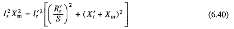
Subtracting Eq. (6.39) from (6.40) yields
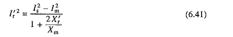
From Eq.(6.39)
The motor torque is
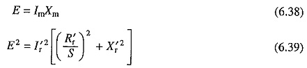
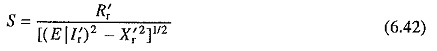
Since Xm is a function of Im, Eqs. (6.38)—(6.42) are non-linear algebraic equations. Use of following steps avoids the need for numerical solution. Assume a value of Im, obtain corresponding E from magnetization characteristic, calculate Xm from Eq. (6.38), obtain I′r from (6.41), calculate S from (6.42) and then ωm and T from Eqs. (6.34) and (6.43), respectively.
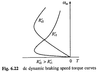
Figure 6.22 Shows the nature of speed torque curves for two values of rotor resistance. In a squirrel-cage motor or a wound-rotor motor without an external resistance in rotor, the maximum torque occurs at low speed. While maximum torque is independent of rotor resistance, speed at which the maximum torque occurs increases with rotor resistance. When Fig. 6.22 dc Dynamic Braking of Induction Motor speed torque curves fast braking is required, a sensationalized resistance is connected in rotor circuit and it is cut-out as speed falls. When used to hold an active load, as in mine winders, a large resistance is connected to obtain speed-torque curves with a negative slope, in order to ensure steady-state stability.
(d) Zero Sequence Braking : In this braking, three stator phases are connected in series across either a single phase ac or a dc source as shown in Fig. 6.23(a). Such a connection is known as a Zero Sequence Connection, because currents in all the stator windings are co-phasal. The mmf caused by co-phasal (or zero-sequence) currents produces a magnetic field having three times the number of poles for which the machine is actually wound. With an ac supply, resultant field is stationary in space and pulsates at the frequency of supply. With dce supply, resultant field is stationary in space and is of constant magnitude. An important advantage of this connection is the uniform loading of all stator phases. The nature of speed-torque curves for ac and dc supply is shown in Fig. 6.23(b). With ac supply, braking could be used only up to one-third of synchronous speed. However, braking torques produced by this connection are considerably larger than motoring. Motor essentially works in regenerative braking. For motors with low rotor resistance, a significant part of generated energy is recovered. Unlike ac Dynamic Braking of Induction Motor, it does not require large rotor resistance, and therefore, can be used both—with squirrel-cage and would-rotor motors.
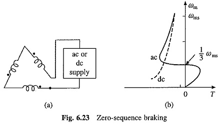
With de supply, braking is available in the entire speed range. It is essentially a dynamic braking as all the generated energy is wasted in rotor resistances. Switching arrangement, from normal three-phase to zero sequence operation, is extremely simple when motor has a delta-connected stator.