Explain Distortion in Amplifier? | Types of Amplifier Distortion:
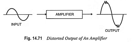
Under ideal conditions, amplified output signal must have exactly the same waveform as the input signal. But in practical amplifiers, this ideal condition is never achieved. Some changes in the waveform may take place in addition to the increase in the amplitude. Such a change is called the distortion and is undesirable because it may change the intelligence (useful information) carried by the signal, as illustrated in Fig. 14.71.
The Distortion in Amplifier may be divided into two broad categories, (nonlinear distortion and linear distortion) depending on the region of the characteristic used by the transistor and the associated circuit and the reactances of the devices.
Nonlinear distortion in amplifier occurs when transistor operates in the nonlinear region of its output characteristic.
- When the signal is viewed in time domain, it is known as the amplitude or waveform distortion.
- When the signal is considered in the frequency domain, it is known as harmonic distortion.
- When the signal applied to the input has more than one frequency (such as speech), it is known as inter-modulation (IM) distortion.
Nonlinear distortion occurs in the case of large signal inputs when the active device is driven into the nonlinear region of its output characteristic.
Linear distortion in amplifier occurs when the active device operates on the linear part of its output characteristic with small signal inputs. It is mainly due to frequency-dependent reactances associated with the circuit or active device itself and occurs when the input signal is composite (the signal having different frequencies say, fundamental and its harmonics). However, the output contains no frequencies other than those at the input.
Linear distortion may be further classified into frequency distortion and phase or delay distortion. The former is due to unequal amplification of different frequencies present in the input signal while the latter is due to unequal phase shift of different signal components.
Amplitude Distortion:
For a small swing of input signal, only a small part of the transconductance curve, as illustrated in Fig. 14.72, is used. This small part is almost linear and operation over this region of the curve is called the linear operation because the changes in the output current are proportional to the changes in input voltage. In such a case, the shape of the amplified waveform is the same as the shape of the input waveform and, therefore, no distortion in amplifier occurs. But for large input signal, the operation becomes nonlinear.
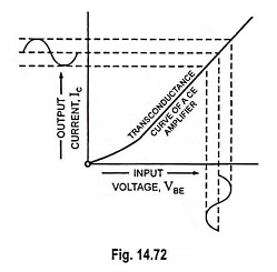
Because of nonlinearity of the transconductance curve, the resulting collector current Ic is no longer truly sinusoidal. The upper half of the wave is elongated. Since this output current flows through a load resistance, the output voltage will also have nonlinear distortion. Such a distortion in amplifier produces new frequency components in the output which are not present in the input signal. These frequencies are usually harmonics of the input frequency.
Harmonic Distortion:
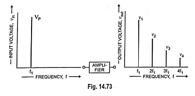
The frequency-domain of nonlinear distortion (harmonic distortion) is depicted in Fig. 14.73. The input is a single-frequency (f1) signal but the output signal consists of dc component and different harmonics. These harmonics are integral multiples of the input signal frequency. The result is that we obtain distorted output. The distortion magnitude depends on the strength and number of these harmonics.
In audio amplifiers employed for amplification of speech or music, the less harmonic distortion, the better performance. For speech, harmonic distortion should not exceed 10% other-wise intelligibility will suffer. High fidelity or hi-fi amplifiers have harmonic and intermodulation (IM) distortion of less than 1 per cent.
Intermodulation Distortion:
The intermodulation distortion occurs when the input signal consists of more than one frequency. If the input signal contains two frequencies f1 and f2, then the output will contain their harmonics i.e., f1, 2f1, 3f1, etc. and f2, 2f2, 3f2, etc. In addition, there would be components (f1 + f2) and (f1 – f2) and also the sum and difference of the harmonics. These sum and difference frequencies are known as intermodulation (IM) frequencies which are undesirable because they subtract from original intelligence. Since IM frequencies are not harmonically related to the input signal, they are easily detectable by human ear as noise. Hence, great care is taken to reduce them to the minimum, particularly in hi-fi audio amplifiers.
Frequency Distortion:
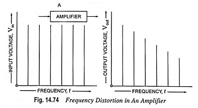
Frequency distortion is caused in an amplifier when signal components of different frequencies are amplified differently. It may occur even with small signal operation. Figure 14.74 illustrates this type of distortion. The input signal spectrum contains many equal amplitude sinusoidal components. Now if the cutoff frequency is less than the highest sinusoidal frequency, the higher frequencies in the output spectrum are attenuated (cutoff). Frequency distortion may be caused either by the electrode capacitances of the amplifying device or by the reactive elements associated with the circuit. In a practical case, frequency distortion is always present and the gain is constant only in the middle frequency range but falls off for low and high frequencies. The quality of speech or music signals is affected by such distortion.
In the design of untuned or wideband amplifiers, special steps are taken to minimize the variation of gain with signal frequency.
Phase or Delay Distortion:
Such a distortion is said to be present when signals of different frequencies suffer unequal phase shift, as illustrated in Fig. 14.75. Because of phase distortion, the third harmonic component changes its phase with respect to the fundamental at the output. Phase distortion is caused by the electronic components used in the amplifier circuit.
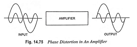
Since human ear is not sensitive to phase shift, the phase distortion has no practical significance in audio amplifiers. If the phase shift varies with frequency, different frequency components of the signal are delayed by different amounts of time and, therefore, a television picture is smeared. Thus in video amplifiers, elimination of phase distortion is significant.
The amount and kinds of distortion that can/cannot be tolerated depend on the particular application of the amplifier. An amplifier that is entirely satisfactory for one application might not be so for another because of the type of distortion introduced by it.