Speed Control of Single Phase Induction Motor using Triac (Fan Regulator):
The conventional speed regulator for a fan uses a resistance regulator. The regulator resistance is in series with the fan motor. The speed of the fan is reduced, whenever desired, by increasing the regulator resistance. Thus the voltage drop across the regulator resistance increases and, therefore, voltage applied to the motor is reduced and so the speed. The resistance regulator causes loss of energy. This loss of energy becomes significant at low speeds.
Working Principle:
Figure 3.55 shows a speed control of single phase induction motor circuit using a diac-triac pair. The diac is meant to trigger the triac into conduction. It is preferable to use a matched diac-triac pair. The R-C circuit forms the triggering network. By adjusting the resistor R, the voltage across capacitor C can be adjusted.
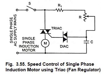
When voltage across capacitor C exceeds breakdown voltage of diac, it is triggered into conduction and sends a triggering signal to the triac gate. When triac is turned on the motor starts.
By varying resistance R, The firing angle of triac can be altered and thus the voltage applied to the motor is changed and consequently the motor speed is changed. Since resistance R, carries very small current, the loss of energy is very small. Sometimes an R-C snubber circuit is added in parallel with the triac to protect it from high voltage transients and high dv/dt.