TRIAC Operation and Characteristics:
The basic construction, equivalent circuit, graphic symbol and TRIAC Operation and Characteristics are shown in Fig. 19-21. The TRIAC behaves as two inverse-parallel connected SCRs with a single gate terminal. Sections n1,p2,n3, and p3, in Fig. 19-21(a) form one SCR that can be represented by transistors Q1 and Q2 in Fig. 19-21(b). Similarly, p1, n2, p2, and n4, form another SCR with the transistor equivalent circuit Q3 and Q4. Layer p2, common to the two SCRs, functions as a gate for both sections of the device. The two outer terminals cannot be identified as anode and cathode; instead they are designated main terminal 1 (MT1) and main terminal 2 (MT2), as illustrated. The TRIAC circuit symbol is composed of two inverse-parallel connected SCR symbols, [Fig. 19-21(c)].
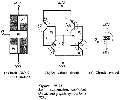
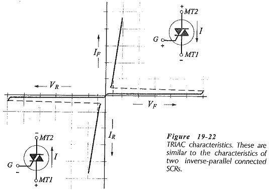
When MT2 is positive with respect to MT1, transistors Q3 and Q4 can be triggered on [Fig. 19-21(b)]. In this case current flow is from MT2 to MT1. When MT1 is positive with respect to MT2, Q1 and Q2 can be switched on. Now current flow is from MT1 to MT2. It is seen that the TRIAC can be made to conduct in either direction. Regardless of the MT2/MT1 voltage polarity, the characteristics for the TRIAC are those of a forward-biased SCR. This is illustrated by the typical TRIAC Operation and Characteristics shown in Fig. 19-22.
TRIAC Triggering:
The characteristics and circuit symbol in Fig. 19-22 show that when MT2 is positive with respect to MT1, the TRIAC can be triggered on by application of a positive gate voltage. Similarly, when MT2 is negative with respect to MT1, a negative gate voltage triggers the device into conduction. However, a negative gate voltage can also trigger the TRIAC when MT2 is positive, and a positive gate voltage can trigger the device when MT2 is negative.
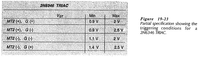
Figure 19-23 shows the triggering conditions for a 2N6346, 8 A, 200 V TRIAC. The voltage polarity for MT2 is identified as MT2(+) or MT2(-), and the gate polarity is listed as G(+) or G(-). From the first line of the specifications, it is seen that with MT2 positive the device gate triggering voltage is +0.9 V minimum and +2 V maximum. From the second line, still with MT2 positive, triggering can be produced by a negative gate voltage; -0.9 V to -2.5 V. The third line shows MT2 negative and the gate trigger voltage as -1.1 V to -2 V. Also, with MT2 negative (fourth line), triggering can be effected by a positive gate voltage; +1.4 V to +2.5 V.
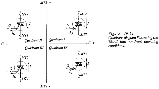
The TRIAC triggering conditions are further illustrated by the diagram in Fig. 19-24. The vertical line identifies MT2 as positive or negative, and the horizontal line shows the gate voltage as positive or negative. The TRIAC Operation and Characteristics is defined as operating in one of the four quadrants: I, II, III, or IV. In quadrant I, MT2 is positive, the gate voltage is positive, and current flow is from MT2 to MT1, as shown. When MT2 is positive and the device is triggered by a negative gate voltage, the TRIAC is operating in quadrant II. In this case, current flow is still from MT2 to MT1. Quadrant III operation occurs when MT2 is negative and the gate voltage is negative. Current flow is now from MT1 to MT2. In quadrant IV, MT2 is again negative, the gate voltage is positive, and current flow is from MT1 to MT2.
Normally, a TRIAC is operated in either quadrant I or quadrant III. When this is the desired condition, it might be necessary to design the circuit to avoid quadrant II or quadrant IV triggering.
DIAC:
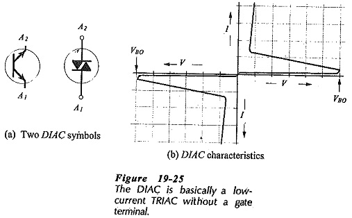
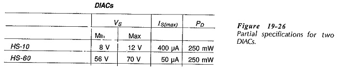
A DIAC is basically a low-current TRIAC without a gate terminal. Switch-on is effected by raising the applied voltage to the breakover voltage. Two different DIAC symbols in general use are shown in Fig. 19-25(a), and typical DIAC characteristics are illustrated in Fig. 19-25(b). Note that the terminals are identified as anode 2 (A2) and anode 1 (A1). Figure 19-26 shows partial specifications for two DIACs. The HS-10 has a switching voltage that ranges from a minimum of 8 V to a maximum of 12 V. Switching current is a maximum of 400 μA. The HS-60 switching voltage is 56 V to 70 V, and maximum switching current is 50 μA. Both devices have a 250 mW power dissipation, and each is contained in a cylindrical low-current diode-type package. DIACs are most often applied in triggering circuit for SCRs and TRIACs.