Varactor Diode Operation and Characteristics:
Varactor Diode Operation and Characteristics were first used in the early 1950s as simple voltage-variable capacitance and later for frequency modulation of oscillators. They thus represent a very mature semiconductor microwave art. As materials and construction improved, so did the maximum operating frequencies, until the stage has now been reached where the most common applications are in tuning, in microwave frequency multipliers and in the very low-noise microwave parametric amplifiers.
Operation:
When reverse-biased, almost any semiconductor diode has a junction capacitance which varies with the applied back bias. If such a diode is manufactured so as to have suitable microwave characteristics, it is then usually called a varactor diode; Figure 12-8 shows its essential characteristics. Apart from the fact that the capacitance variation must be appreciable in a varactor diode, it must be capable of being varied at a microwave rate, so that high-frequency losses must be kept low. The basic way in which such losses are reduced is the reduction in the size of the active parts of the diode itself.
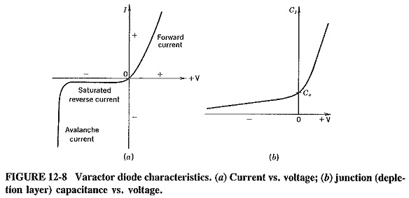
In a diffused-junction diode, the junction is depleted when reverse bias is applied, and the diode then behaves as a capacitance, with the junction itself acting as a dielectric between the two conducting materials. The width of the depletion layer depends on the applied bias, and the capacitance is naturally inversely proportional to the width of this layer; it may thus be varied with changes in the bias. This is shown in Figure 12-8b, where C0 represents the junction capacitance for zero bias voltage. Finally, as with all other diodes, avalanche occurs with very high reverse bias. Since this is likely to be destructive, it forms a natural limit for the useful operating range of the diode.
Materials and construction:
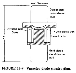
Diffused-junction mesa silicon diodes were used originally at microwave frequencies, but by now they have to a large extent been supplanted by gallium arsenide varactors. Figure 12-9 shows a Varactor Diode Operation and Characteristics made of gallium arsenide. GaAs has such advantages as a higher maximum operating frequency (up to nearly 1000 GHz) and better functioning at the lowest temperatures (of the order of – 269°C, as in parametric amplifier applications). Both advantages are due mainly to the higher mobility of charge carriers exhibited by gallium arsenide.
Characteristics and requirement:
Above all, the Varactor Diode Operation and Characteristics (no matter how it is made or what it is made from) is a diode, i.e., a rectifier. The diode conducts normally in the forward direction, but the reverse current saturates at a relatively low voltage (as Figure 12-8a shows) and then remains constant, eventually rising rapidly at the avalanche point. For varactor applications, the region of interest lies between the reverse saturation point, which gives the maximum junction capacitance, and a point just above avalanche, at which the minimum diode capacitance is obtained. Conduction and avalanche are thus seen to be the two conditions which limit the reverse voltage swing and therefore the capacitance variation.
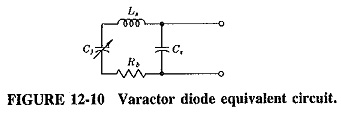
Within the useful operating region, the varactor diode at high frequencies behaves as a capacitance in series with a resistance. At higher frequencies still, the stray lead inductance becomes noticeable, and so does the stray fixed capacitance between the cathode and anode connections. The equivalent circuit diagram of Figure 12-10 then applies. For a typical silicon varactor, C0 = 25 pF, Cmin = 5 pF, Rb = 1.3 Ω, Cs = 1.4 pF, and Ls = 0.013 μH.
To be suitable for parametric amplifier service, a varactor diode should have a large capacitance variation, a small value of minimum junction capacitance and the lowest possible value of series resistance Rb (to give low noise). For harmonic generation, much the same requirements apply (although possibly the low value of Rb is a little less important), but now power-handling ability assumes a greater significance. Base resistance and minimum junction capacitance are largely tied to each other, so that these two requirements can be satisfied only in a compromise fashion. The resistive cutoff frequency is often used as a figure of merit; it is given by
![]()
Values of fc well over 1000 GHz are available from gallium arsenide varactors. However, this does not mean that varactors may be operated at such high frequencies. The fc is measured at a relatively low frequency (e.g., 50 or 500 MHz). It is a figure of merit, a convenient way of relating base resistance and minimum junction capacitance. Operation at frequencies much above fc/10 is inadvisable, because at such frequencies there is a gradual increase in base resistance, partly through the skin effect. Consequently the diode Q drops, and the result is increased noise in parametric amplifiers or increased dissipation (lowered efficiency) in frequency multipliers.
Frequency multiplication mechanism:
It was shown earlier that the output current resulting from the application of an ac voltage to a nonlinear resistance is not merely proportional to this voltage. In fact, coefficients of non-linearity exist, and the output current is thus in part dependent on the square, cube and higher powers of the input voltage. It showed that, if the square term is taken into consideration, the output voltage contains the second harmonic of the input current. Had higher non-linearity terms been included in the expansion, third and higher harmonics of the input would have been shown to be present in the output of such a nonlinear resistance.
Unfortunately, this type of frequency multiplication process is not very efficient, because the coefficient of non-linearity is not usually very large. Moreover, if this impedance is a pure reactance, the frequency multiplication process may be 100 percent efficient in theory.
Since the capacitance of a varactor diode varies with the applied reverse bias, the diode acts as a nonlinear capacitance (i.e., a nonlinear capacitive reactance). The Varactor Diode Operation and Characteristics is consequently a very useful device, especially since it will operate at frequencies much higher than the highest operating frequencies of transistor oscillators.