Operation of Synchronous Motor:
Operation of Synchronous Motor – For any speed other than synchronous speed, the relative speed between air gap flux wave and the rotor is not zero. Consequently, δ varies from 0 to 360°, and torque fluctuates between positive and negative values, but its average value remains zero. Frequency of torque fluctuations depends on the relative speed between air-gap flux wave, which rotates at synchronous speed, and the rotor. When rotor is at stand-still, the frequency is too high for the rotor inertia to allow any change in speed. Consequently, the motor is not self starting.
If rotor is brought close to synchronous speed by some starting method and then dc field is excited, the synchronous torque assisted by the damper winding torque is able to pull the rotor into step with the rotating field after a short duration of hunting, and the machine then works as a Operation of Synchronous Motor. The process of pulling rotor into step with the rotating field is called pull-in or synchronisation.
Starting:
As stated above, the purpose of starting method is to bring rotor speed close to synchronous speed. One widely used method is to start the synchronous, motor as an induction motor with field unexcited and damper winding serving as a squirrel-cage rotor. Following should be noted about this starting method:
- The starting torque and current can be increased and reduced respectively, by increasing the damper winding resistance. For successful pull-in, the motor speed while running as an induction motor must be close to synchronous speed. For this the damper winding resistance must be as low as possible. Further, for damping hunting oscillations, damper winding resistance must be low. The damper winding resistance is chosen to provide a compromise between these contradictory requirements.
- During acceleration as an induction motor, because of large number of turns in field winding, the induced voltage in the field winding may reach several thousand volts, thus overstressing the insulation of the winding and increasing the voltage rating of the field supply converter. This undesirable situation is eliminated by keeping the field circuit closed through a small discharge resistance before dc excitation is applied. The discharge resistance permits a circulating current
- to flow through the field winding. Though induced voltage is still present, the actual potential difference between terminals or between turns is reduced to a safe value.
- The field closed through a discharge resistance, acts somewhat as a cage winding and modifies the starting and pull-in-torques. An increase in the field circuit resistance increases the starting torque. On the other hand, a decrease in discharge resistance reduces the potential difference appearing in the field circuit. The value of discharge resistance is chosen to obtain a compromise between these two constradictory requirements.
- dc excitation should not be applied during acceleration as an induction motor because while it produces no net motoring torque, it does produce braking torque (braking torque is produced by the currents that are induced in stator by the dc field). dc field should be applied only after the motor has reached close to full speed.
- When rotor has salient pole construction, the damper winding can have conductors only over the pole arc. This leads to a dip in the speed-torque curve at half of synchronous speed.
- When started with full supply voltage, the starting current can be 7 to 10 times of full load Except in small size motors, such a high starting current causes fluctuations in supply voltage. In case of large size motors, such a high starting current may cause a large drop in the terminal voltage, thus reducing the already low starting torque further. Starting current can be reduced by employing any one of the reduced voltage starting methods employed for induction motors. Reduction in starting current is obtained at the expense of reduction in starting torque. When started at a reduced voltage, the transition to full voltage can be made before or after the pull-in. Former is preferred as it improves pull-in performance due to two reasons: (1) with full voltage the speed attained as induction motor is closer to synchronous speed and (2) the pull-in torque increases in proportion to voltage squarred, consequently pull-in can be achieved faster and with larger motor loads.
Another method of starting is to use a low power auxiliary motor coupled to the synchronous motor shaft. With the help of auxiliary motor, the rotor speed is brought near, synchronous speed and then dc field is switched-in. This method has a very low starting torque.
Pull-in:
Pull-in process begins when the field supply is switched-in. When pull-in takes place at no load or at light loads, field supply can be switched-in without regard to the value of torque angle at the instant of switching. This may give rise to considerable disturbance in line currents during the pull-in process, with their magnitudes going well above the rated value. Since, before pull-in is completed, rotor speed will be less than synchronous speed, the rotor may slip several poles of air-gap flux wave before reaching synchronous speed. In case of salient pole motors, the rotor may be brought to synchronous speed by reluctance torque prior to the application of field supply. However, this would occur without regard to eventual polarity of the rotor poles. If polarity is right the pull-in will take place with minimum disturbance. If wrong, the rotor may slip several poles before pull-in is completed.
When faster pull-in is desired or pull-in condition is somewhere near critical owing to substantial load on the motor, the field is excited at the most favourable angle. When running at top speed as an induction motor, rotor speed will be less than the synchronous speed. When dc field is applied, rotor poles will slip backward with respect to the poles of the rotating field. Consequently, δ will be constantly changing. The torque will be negative for range of δ from 0 to 180° leading.
In this range, the synchronous torque will decelerate the rotor. Torque will be positive for δ from 0 to 180° lagging, hence synchronous torque will accelerate the rotor. Rotor will be subjected to the accelerating torque of longest duration when the field is excited at δ= 0°. Hence, δ= 0° is the most favorable angle for exciting dc field. At this instant (i.e. δ = 0°), south pole of the rotating field coincides with north pole of the rotor and vice versa. Hence, flux linkage with rotor poles will be maximum and in the same direction that they will have when the field is energised. Consequently, the induced voltage in the field winding will be zero. Since field circuit is inductive, current flowing through it will lag the induced voltage. Therefore, δ will be zero when the field current is negative and increasing. This information about the field current can be utilised to sense the most favourable angle.
Transients Due to Load Disturbances:
It is important to predict the ability of a Operation of Synchronous Motor to remain in synchronism after a load disturbance occurs.
Steady State Stability Limit:
From Eq. (7.4)
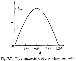
T-δ characteristic is shown in Fig. 7.7. If load torque TL is slowly applied, torque angle δ will increase. When TL becomes equal to Tmax, δ will reach 90°. If load torque is increased further, the motor will lose synchronism because motor torque will be less than the load torque. For a load torque which increases slowly, maximum load torque that the motor can hold without losing synchronism is Tmax, which is known as the steady-state stability limit of Operation of Synchronous Motor.
Dynamic Stability:
If a load torque TL is applied suddenly, motor may lose synchronism even if load torque is less than maximum torque that the motor can develop. When load torque is changed suddenly, whether the motor will retain synchronism or not can be determined by examination of the dynamic behavior of Operation of Synchronous Motor.
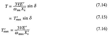
Under transient Operation of Synchronous Motor can be represented by the equivalent circuit of Fig. 7.1 by replacing E by E’ and Xs by X′s, where E’ is the voltage behind transient reactance X′s before disturbance and is determined by the equation E’ = V – iIs X′s. Motor torque is now given by
Torque balance equation of the Operation of Synchronous Motor is
where Ta =Kj d2δ/dt2 is the acceleration torque and Td = Kd dδ/dt2 is the damping torque
Equation (7.17) can now be written as
Equation (7.18) is a nonlinear differential equation. It can be solved numerically to obtain variation of δ with time, and thus, ascertain the dynamic stability of motor load system.
Braking:
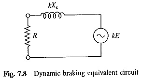
As shown in Fig. 7.3, the motor can work in regenerative braking only at synchronous speed. Therefore, regenerative braking cannot be used for stopping or decelerating a load. Dynamic braking is obtained by disconnecting stator from the source and connecting it to a three-phase resistor. Machine works as a synchronous generator and dissipates generated energy in the braking resistor. The per phase equivalent circuit for a per unit speed k is shown in Fig. 7.8.
The per unit speed k is given by
braking current
braking power
braking torque
Substitution from (7.20) and (7.21) gives
Since synchronous reactance is large compared to braking resistance, for most speed range, the variation of current and torque is not large. Therefore, a single section of resistance is enough. At zero speed, the induced voltage, and therefore, armature current and torque are zero. As the torque is available in whole speed range and it is zero at zero speed, dynamic braking is suitable for stopping motor.
Theoretically, plugging can also be employed. However, it is not used in practice. Plugging torque is produced by damper winding. Because of its low resistance, while current drawn from the supply is very large, the braking torque produced is much smaller compared to that produced by dynamic braking. In case of large motors, high plugging current can create a severe disturbance in supply lines.


