Slip Power Recovery Scheme used in Induction Motor:
Slip Power Recovery Scheme used in Induction Motor – Figure 6.53 shows an equivalent circuit of a wound-rotor induction motor with voltage Vr injected into its rotor, assuming stator-to-rotor turns ratio unity. When rotor copper loss is neglected
![]()
where Pr is the power absorbed by the source Vr. The magnitude and sign of Pr can be controlled by controlling the magnitude and phase of Vr. When Pr is zero, motor runs on its natural speed torque characteristic. A positive Pr will reduce Pm, and therefore, motor will run at a lower speed for the same torque. When Pr is made equal to Pg, then Pm and consequently speed will be zero. Thus, variation of Pr from 0 to Pg will allow speed control from synchronous to zero speed. Polarity of Vr for this operation is shown in Fig. 6.53 by a continuous line.
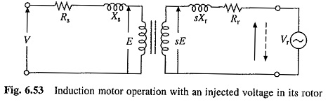
When Pr is negative, i.e. Vr acts as a source of power, Pm will be larger than Pg and motor will run at a speed higher than synchronous speed. Polarity of Vr for speed control above synchronous speed is shown by a dotted line in Fig. 6.53.
When rotor copper loss is neglected, Pr is equal to Slip Power Recovery Scheme used in Induction Motor, sPg. Speed control below synchronous speed is obtained by controlling the slip-power. the same approach was adopted in rotor resistance control. However, instead of wasting power in external resistors, it is usefully employed here. Therefore, these methods of speed control are classified as Slip Power Recovery Scheme used in Induction Motor recovery schemes. Two such schemes, Static Sherbius and Static Kramer Drives, are described here.
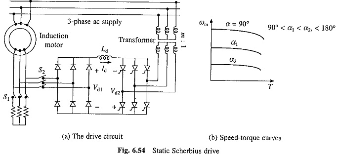
Static Scherbius Drive (Fig. 6.54(a)):
It provides the speed control of a wound rotor motor below synchronous speed. A portion of rotor ac power is converted into dc by a diode bridge. The controlled rectifier working as an inverter converts it back to ac and feeds it back to the ac source. Power fed back (i.e. Pr) can be controlled by controlling inverter counter emf Vd2, which in turn is controller by controlling the inverter firing angle. The dc link inductor is provided to reduce ripple in dc link current Id.
Since Slip Power Recovery Scheme used in Induction Motor is fed back to the source, unlike rotor resistance control where it is wasted in resistors, drive has a high efficiency. The drive has higher efficiency than stator voltage control by ac voltage controllers because of the same reasons.
Drive input power is the difference between motor input power and the power fed back. Reactive input power is the sum of motor and inverter reactive powers. Therefore, drive has a poor power factor throughout the range of its operation.
From Fig. 6.54(a), neglecting stator and rotor drops
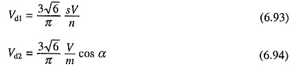
where α is the inverter firing angle and, n and m are, respectively, the stator to rotor turns ratio of motor and source side to converter side turns ratio of the transformer. Neglecting drop across inductor
![]()
Substituting from Eqs. (6.93) and (6.94) yields
![]()
where a = n/m.
Maximum value of α is restricted to 165° for safe commutation of inverter thyristors. Slip can be controlled from 0 to 0.966a when α is changed from 90 to 165°. By appropriate choice of a, required speed range can be obtained.
Transformer is used to match the voltages Vd1 and Vd2. At the lowest speed required from the drive, Vd1 will have the maximum value Vd1m given by
![]()
where smax, is the value of slip at the lowest speed. If α is restricted to 165°, m is chosen such that the inverter voltage has a value Vd1m when α is 165° i.e.
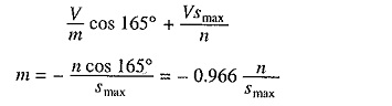
Such a choice of m ensures inverter operation at the highest firing angle at the lowest motor speed, giving highest power factor (Eqn. (5.109)) and lowest reactive power at the lowest speed. This improves the drive power factor and reduces reactive power at all speeds in the speed range of the drive.
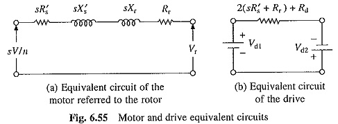
Figure 6.55(a) shows equivalent circuit of motor referred to the rotor, neglecting magnetizing branch. Derivation of Eq. (6.90) shows that when referred to dc link, resistance (sR′s + Rr) will be 2(sR′s + Rr). This gives approximate dc equivalent circuit of the drive (Fig. 6.55(b)), where Vd1 and Vd2 are given in Eqs. (6.93) and (6.94). Rd is the resistance of dc link inductor. Equivalent circuit ignores the commutation overlap in the diode bridge. Now
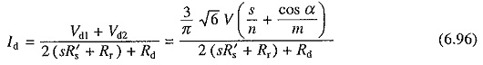
If rotor copper loss is neglected
The nature of speed torque curves is shown in Fig. 6.54(6).
The drive has applications in fan and pump drives which require speed control in a narrow range only. If maximum slip is denoted by smax, then power ratings of diode bridge, inverter and transformer can be just smax times the motor power rating (Eq. 6.97). For example, when speed is to be reduced below synchronous speed by only 20%, power ratings of diode bridge, inverter and transformer will be just 20% of motor power rating. Consequently, drive has a low cost.
Drive is started by resistance control with S1 closed and S2 open (Fig. 6.54). When speed reaches within control range of the drive, S2 is closed to connect diode bridge and inverter is activated. Now S1 is opened to remove the resistances.
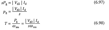
In fan and pump drives braking is not required, because the fluid pressure provides adequate braking torque. To maintain constant fluid flow with variations in pressure head and the nature of pumped fluid, the drive is operated with a closed loop speed control. A close loop speed control scheme with inner current control is shown in Fig. 6.56. It operates in the same way as the scheme of Fig. 3.5.
This drive is widely used in medium and high power (up to around 10 MW) fan and pump drives, because of high efficiency and low cost.
This drive provides a constant torque control (Eqn. (6.98)). Constant power control is obtained by static Kramer drive described below.
Static Kramer Drive:
Rotor slip power is converted into dc by a diode bridge (Fig. 6.57(a)). The dc power is now fed to dc motor mechanically coupled to induction motor. Torque supplied to load is sum of torque produced by induction and dc motors. Speed control is obtained by controlling field current of dc motor.
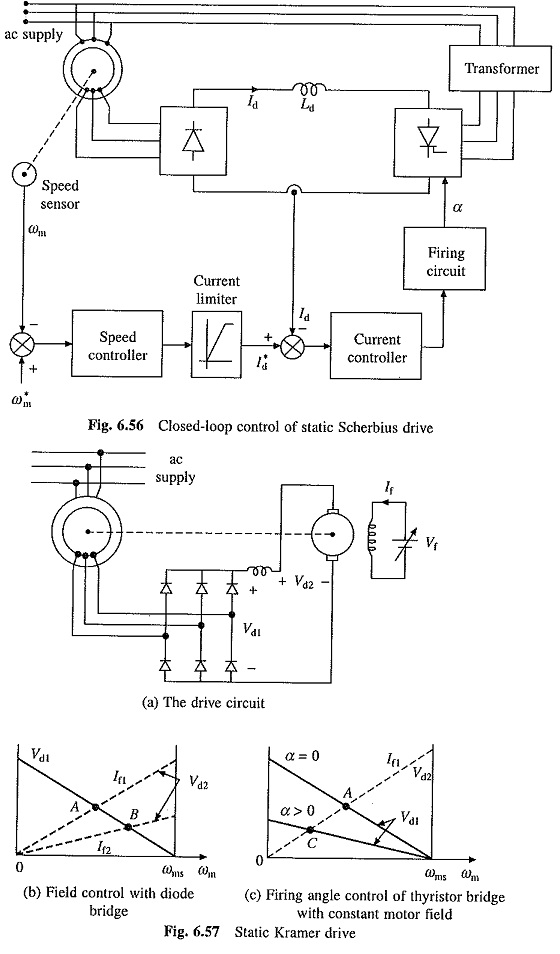
Figure 6.57(b) shows variations of Vd1 and Vd2 with speed for two values of dc motor field current. The steady state operation is obtained when Vd1 = Vd2, i.e. at A and B for field currents If1 and If2. Speed control is possible from synchronous speed to around half of synchronous speed. When larger speed range is required, diode bridge is replaced by a thyristor bridge. Now relationship between Vd1 and speed can be altered by controlling firing angle of thyristor rectifier (see Fig. 6.57(c)). Speed can now be controlled up to standstill.