Synchronous Motors Types:
Commonly used Synchronous Motors Types are: wound field, permanent magnet, synchronous reluctance and hysteresis motors. All these motors have a stator with a 3-phase winding, which is connected to an ac source. Fractional horse power synchronous reluctance and hysteresis motors employ a 1-phase stator.
Wound field synchronous motor rotor has a dc field winding, which is supplied from a dc source through slip-rings and brushes. The rotor can have cylindrical or salient pole construction. Cylindrical rotor motors have higher mechanical strength and are employed in high power and high speed applications; for other applications salient pole motors are preferred due to lower cost.
In medium and small size motors, dc field can be produced by permanent magnets. Thus, dispensing with dc source, slip-rings, brushes and field winding losses. Such motors are known as Permanent Magnet (PM) Synchronous Motors. Usually ferrite magnets are employed. Rare earth (cobalt-samarium) magnets, although very expensive, are some times used to reduce the volume and weight of the motor.
Permanent Magnet Synchronous Motors Types are classified as:
-
surface mounted and
-
interior (or buried).
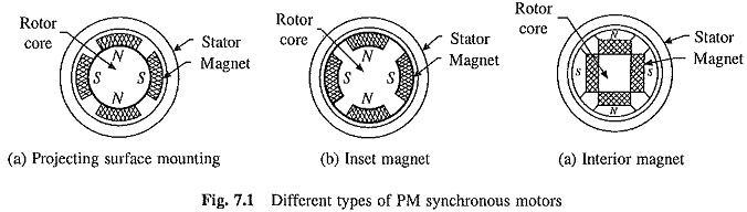
Surface mounted PM motors are of two types: (1) projecting type, in which magnets project from the surface of rotor (Fig. 7.1(a)), and (2) inset type, in which magnets are inserted into the rotor, providing a smooth rotor surface (Fig. 7.1(b)). Epoxy glue is used to fix the magnets to the rotor surface in both. While these motors are easy to construct and are less expensive, they are less robust compared to interior type (Fig. 7.1(c)) rotors and are not suitable for high speed applications. In interior type PM motors, magnets are imbedded in the interior of the rotor.
The wound field and permanent magnet Synchronous Motors Types have a higher full load efficiency and power factor than an induction motor. Wound field motors can be designed for a higher power rating than induction motors. Since the air-gap flux is not produced solely by the magnetizing current drawn from the armature, a larger air-gap suiting the mechanical design can be chosen. The ability to control power factor is an important advantage at higher power levels. Operating at unity power factor minimizes the inverter rating. Apart from the robust construction, permanent magnet synchronous motor has low losses and high efficiency. Because of low losses, it is possible to make motors with very high power density and torque to inertia ratios. These make them suitable for servo drives requiring fastest possible dynamic response.
The rotor of a synchronous reluctance motor has salient poles but neither have field winding nor permanent magnets. Motor is driven by reluctance torque which is produced due to tendency of the salient rotor poles to align themselves with synchronously rotating field produced by the stator.
All the above mentioned Synchronous Motors Types, when designed to operate with a source of fixed frequency, are provided with damper winding, which is similar to squirrel-cage winding of an induction motor. It is used to start the machine as induction motor and to damp the hunting oscillations which occur during the transient operations. When fed from a variable frequency source, capable of smooth frequency variation from zero to rated, the damper winding is not required for starting. It may, however, be required for damping hunting oscillations or for some other purposes explained later.
One important difference between the wound field and permanent magnet motors, which are designed to operate with a source of fixed frequency, must be noted. When a wound field motor is started as an induction motor, dc field is kept off. In case of a permanent magnet motor, the field cannot be ‘turned off’. When at a speed below synchronous speed, the rotor field induces a voltage in the stator, which has a frequency different than the frequency of stator supply. The current produced by induced voltage interacts with the rotor field to produce a braking torque, which opposes induction motor torque due to damper winding. The permanent magnet synchronous motor (PMSM) is designed so that the braking torque is very small compared to induction motor torque. Because of the capability to start direct on line these motors are called line start PMSM. They are available in 3-phase and 1-phase construction. Although expensive compared to induction motors, they have advantages of high efficiency, high power factor and low sensitivity to supply voltage variations. Therefore, they are preferred for industrial applications with large duty cycles such as pumps, fans and compressors.
The hysteresis synchronous motors are employed in low power applications requiring smooth start and quiet operation.
Cylindrical Rotor Wound Field Motor:
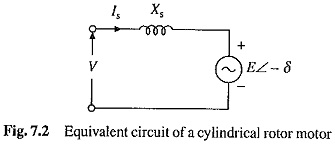
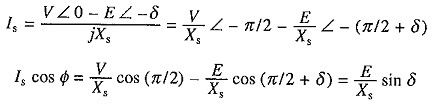
A simplified per phase equivalent circuit of a cylindrical rotor motor is shown in Fig. 7.2. Xs is the synchronous reactance and E is known as excitation emf. From Fig. 7.2, power input to the motor is
![]()
where Φ is the phase angle of Is with respect to V.
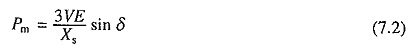
Since stator loss has been neglected, the power developed is
![]()
From Fig. 7.2,
Substitution Eq. (7.1) gives
The rotating field produced by stator moves at a synchronous speed which is given by
where f is the supply frequency and p the number of poles.
For a steady torque to be produced, rotor field must move at the same speed as stator field. Since rotor field has same speed as that of rotor, the rotor also runs at synchronous speed. Therefore, torque is
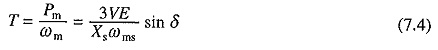
For a given field excitation, E is constant. Therefore, Pm and T are proportional to sin δ. The angle δ is called power (or torque) angle.
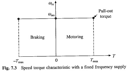
The speed torque curve is shown in Fig. 7.3. The motoring operation is obtained when δ is positive and E lags being V, whereas regenerative braking is obtained when δ is negative or E leads V. The maximum torque Tmax (also known as pull-out torque), is reached at δ = ± 90°. If the load torque exceeds Tmax, the machine pulls out of synchronism. In order to prevent damage due to excessive current, automatic circuit breakers are provided to disconnect the machine when it comes out of synchronism.
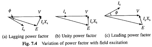
The important feature of wound field motor is that its power factor can be controlled by varying field current (or E). The machine phasor diagrams for a given developed power are shown in Fig. 7.4. When field excitation is small, the machine operates with a lagging power factor. The power factor can be made unity or leading by increasing the field excitation.
Salient Pole Wound Field Motor:
Because of different synchronous reactances in direct and quadrature axes, the machine cannot be described by a simple equivalent circuit. From the phasor diagram (Fig. 7.5):
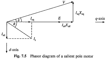
![]()
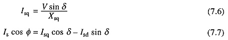
where Xsd and Xsq are respectively synchronous reactances of direct and quadrature axes; and Isd and Isq are respectively direct and quadrature components of Is.
Substituting from Eqs. (7.5) and (7.6) into (7.7), yields
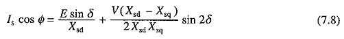
Substituting in Eq. (7.1) gives
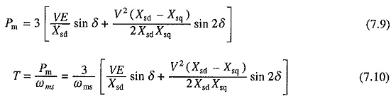
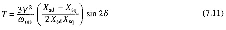
The torque expression has two components. First component (synchronous torque) is proportional to sin δ, and the second component (reluctance torque) is proportional to sin 2δ. The speed-torque characteristic is similar to that shown in Fig. 7.3.
Permanent Magnet Motor:
In this motor, field excitation is obtained by mounting permanent magnets on the rotor. This eliminates dc source, losses associated with the field winding and frequent maintenance associated with slip rings and brushes in a wound field motor. But then the power factor cannot be controlled because the field excitation cannot be changed. These motors are usually designed to operate at unity power factor at full load. While projecting type machine has an uniform air-gap, the inset and interior types have essentially salient-pole construction. Therefore, power and torque expressions of Eqs. (7.2) and (7.4) are applicable to projecting type surface magnet machines and those of (7.9) and (7.10) are applicable to buried (or interior) and inset type surface magnet machines.
Synchronous Reluctance Motor:
A reluctance motor can be visualized as a salient pole motor without a field winding. Therefore, an expression for torque is obtained by substitution of E = 0 in Eq. (7.10). Thus
Due to the absence of field excitation, air-gap flux is produced only by magnetising current drawn from the source. Therefore, magnetising current is larger and power factor is lower compared to other Synchronous Motors Types.
Damper Winding:
Some Synchronous Motors Types described above have an additional winding, known as damper or amortisseur winding, on the rotor. It is similar to squirrel-cage winding of an induction motor. It is provided to damp hunting oscillations which occur during transient operation of the motor. It is also used to start the motor as an induction motor. When the motor runs at synchronous speed, no voltages are induced in the damper winding. Therefore, damper winding has no effect on motor operation.
Hysteresis Synchronous Motor:
The stator of a hysteresis motor has single-phase (capacitor run type) or three-phase ac winding. Rotor consists of a single thin-walled cylinder made of hard, heat-treated steel. Cross-sectional view of the rotor is shown in Fig. 7.6.
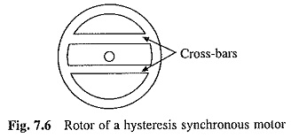
Below the synchronous speed motor works as an induction motor. Cylinder forms the rotor winding. When rotating, field produced by the Cross-bars stator moves past the rotor, voltages are induced in the cylinder causing current to flow. The rotor is made of hard steel in which hysteresis and eddy-current losses take place. Since hysteresis loss is proportional to frequency and eddy-current loss proportional to square of frequency, the equivalent rotor resistance (which accounts for these losses) decreases with frequency and therefore has a high value at stand-still and decreases as the rotor speed increases. As a consequence of this, the motor has low starting current and it develops nearly a constant torque at subsynchronous speeds. Because of low starting current (nearly 1.5 times rated) and moderate torque, it is suitable for high inertia loads.
At synchronous speed, the machine operates similar to a reluctance motor. Rotor has the lowest reluctance path for the flux along the crossbars. Poles are induced in rotor with magnetic north and south poles aligning along the lines of crossbars. The poles thus formed lock into synchronisation with rotating stator field.
When a stationary motor is connected to the source, it accelerates fast and smoothly as an induction motor and when very close to the synchronous speed it smoothly pulls into step, without any hunting oscillations. Once the synchronous speed is reached, voltages are not induced in the rotor and hysteresis and eddy current losses reduce to zero.
Since the rotor has smooth non-salient construction, its operation is smooth and quiet. Small hysteresis motors are extensively used in tape recorders, office equipment and fans. Because of the low starting current, it finds application in high inertia applications such as gyro compasses and small centrifuges.
Inductor Machine:
The inductor machine is a special type of synchronous generator designed to operate at high speed. The rotor has several teeth and no winding, which makes it rugged and capable of running at high speeds. The stator has dc field winding and armature winding. When the dc field winding is excited it produces unidirectional stationary field. When the rotor rotates, magnetic circuit reluctance varies in a cyclic manner, producing similar variations in flux. Alternating voltages are generated in armature winding on the stator. Inductor machines are used as auxiliary power generators in applications where main prime mover speed is very high, e.g. in aircrafts where engine speeds can be as high as 100,000 rpm.