Margin Angle Control of Synchronous Motors:
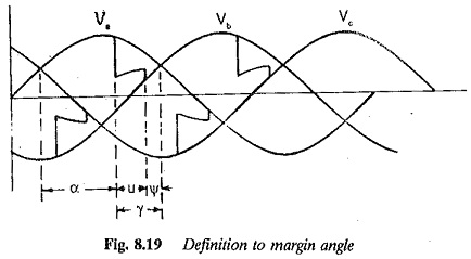
The commutation Margin Angle Control of Synchronous Motors is defined as the angle measured from the end of commutation to the crossing of the phase voltage which was under commutation (natural firing instant). For satisfactory operation, without commutation failure, this margin angle must be greater than the turn off angle (ωtq) of the thyristors. In the constant Margin Angle Control of Synchronous Motors it is always observed that the margin angle does not go below a minimum value. Referring to Fig. 8.19 the margin angle is
![]()
where
γ is the lead angle of firing and
u is the overlap angle.
Among the factors, which influence the angle of overlap is the dc link Under transient conditions u increases. The value of γ also increases so that ψ remains the same, Obviously the performance improves as commutation failure cannot occur. On the other hand, in the constant lead angle control the margin angle decreases with increase in u, resulting in a commutation failure. In the control, therefore, the firing angle changes such that the necessary lead angle of firing is available to keep ψb constant in case u changes. The overlap angle of the converter must be known and fed to the microprocessor. Microprocessor control of self controlled synchronous motor, discussed previously, may be used if the necessary changes are made in the firing of the converter, based on the information available on the margin angle and overlap. The method of implementing the Margin Angle Control of Synchronous Motors is discussed in the following.
There are two ways of implementing the constant margin angle control:
- The margin angle ψ is detected and controlled directly.
- Control is effected invoking the relationship between the link current Id and the margin angle ψ. The margin angle is controlled using a function j generator or a correction as a function of Id.
In the first method the value of margin angle can be controlled to be constant at a value which gives a satisfactory transient and steady-state performance. However, the direct detection of margin angle is difficult over a wide range of speeds, due to ripple present in the machine voltage. This ripple causes difficulties in the detection of zero crossing of the voltages. The second method does not require the detection of Margin Angle Control of Synchronous Motors and hence is very practical in the control of synchronous motors. The overlap angle is detected and is used in the control.
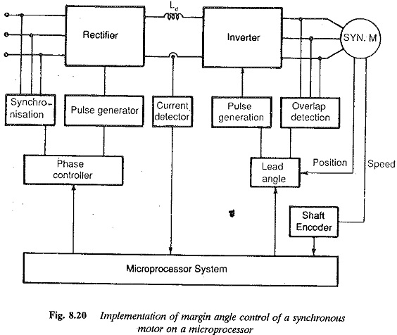
The method of control depicted in Fig. 8.20 is as follows. For a given value of margin angle, the relation between the lead angle of firing γ = 180 – α and the link current is calculated. The relation is stored in the memory as a look-up table (function generation). This table is used by the microprocessor to correct the lead angle of firing in terms of Id and u.
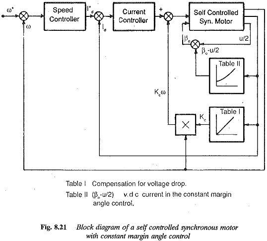
There are several difficulties with the Margin Angle Control of Synchronous Motors which require careful study, so that the control can be made advantageous. The constant margin angle control results in an intrinsic instability due to a voltage drop associated with overlap. Investigations show that the motor has unstable operation q. at heavy currents and high speeds. The motor can be stabilised by compensating the voltage drop due to overlap. A loop providing counter emf compensation corrects the voltage drop using the relation between Id and loop gain in Kc in volts per rpm (Fig. 8.21).
The second difficulty arises from the transient behaviour of the margin angle, i.e., variation of ψ with Id in transient conditions. The lookup table used for steady-state. conditions may not be satisfactory under transient conditions due to change in ψ. Commutation failure may occur. The Margin Angle Control of Synchronous Motors depends upon the overlap u which increases with rapid increase in the dc current. Therefore, the transient behaviour of ψ affects the commutation, which may fail if Id increases very rapidly. A long time delay in gate pulses may also cause this failure. Therefore, a digital simulation of the system must be carried out to study the behaviour of the margin angle. The reference value is set at a safe value taking the variation of ψ with Id into consideration so that in any case there is no commutation failure.
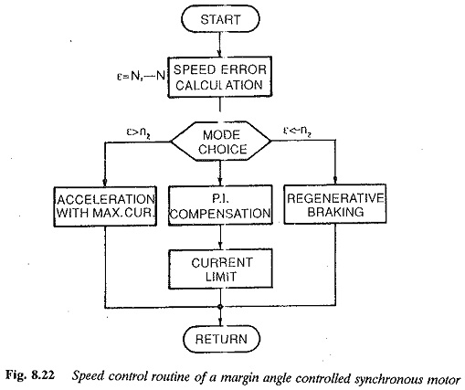
The microprocessor control of a synchronous motor incorporating margin angle control is shown in Fig. 8.22. The control is achieved as a four quadrant drive with regeneration facilities. The error of the speed controller decides the mode of operation, e.g., acceleration, regeneration or motoring. If the speed error ε is greater than a set value n2, the mode of operation is regeneration. The line side converter operates as an inverter reversing the polarity of link voltage. Accordingly regeneration is performed. This error also decides the acceleration (ε > – n1). The acceleration is obtained with maximum current. The constant Margin Angle Control of Synchronous Motors is employed and care is taken to see that there is no commutation failure at the maximum current. In the region of errors – n1< ε < n2 the normal PI compensation takes place with a current reference to current controller.
The current control processing routine comprises compensation of induced voltage, PI control and arc cosine compensation.
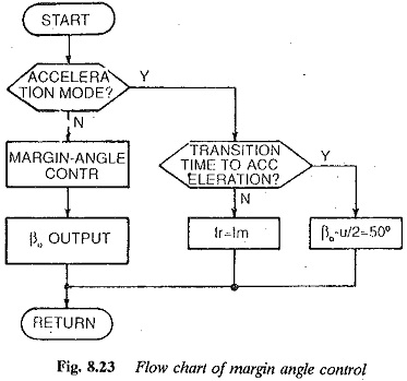
The Margin Angle Control of Synchronous Motors routine is shown in Fig. 8.23. This control takes place in the accelerating mode. When the drive is in this mode and the transition index is set, the margin angle is maintained at a proper value so that the commutation failure due to rapid increase in Id is prevented.
The speed control routine in PI mode is performed with steady-state ψ control.
Selection of microprocessor: The criteria for selecting a microprocessor for controlling a synchronous motor discussed as above, are more or less the same as those discussed in the examples of dc motor and induction motor. The resolution of firing angle, instruction and cycle time, interrupt capability, and arithmetic operations, including the capacity to support multiplication and division, are several of the criteria based on which the selection can be made. The type of microprocessor selected should have sufficient memory capacity. It may be selected based on the number of bits, memory access time, I interrupt I/O interface, kinds and number of instructions, reliability, cost and productivity. The future needs for development also may be considered. The local hardware design must consider the capacity of the microprocessor chosen.The necessary interfaces are required in the form of A/D converters or others to convert the measured analog signals to digital quantities for processing by the microprocessor. The necessary software supports may be provided to generate firing pulses. If the capacity is limited these pulses may be generated by the necessary hardware to save the processor time for other jobs.
The microprocessor may be employed to control a synchronous motor using a cycloconverter, PWM inverter, etc. The cycloconverter fed synchronous motor can be used for low speed reversing mills. Both machine commutation and line commutation may be employed. The PWM inverter operation provides the necessary voltage and harmonic controls, so that the low speed operation of the motor is smooth with least torque pulsation.