Impedance and Phase Angle of Series Resonant Circuit:
The impedance of a Series Resonant Circuit is
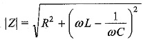
The variation of XC and XL with frequency is shown in Fig. 8.4.
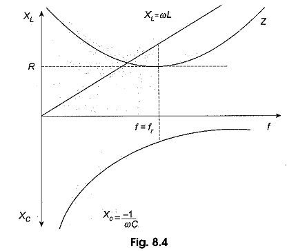
At zero frequency, both XC and Z are infinitely large, and XL is zero because at zero frequency the capacitor acts as an open circuit and the inductor acts as a short circuit. As the frequency increases, XC decreases and XL increases. Since XC is larger than XL, at frequencies below the resonant frequency fr, Z decreases along with XC.
At resonant frequency fr, XC = XL, and Z = R. At frequencies above the resonant frequency fr, XL is larger than XC, causing Z to increase. The phase angle as a function of frequency is shown in Fig. 8.5.
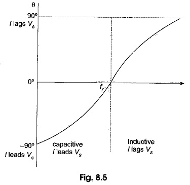
At a frequency below the resonant frequency, current leads the source voltage because the capacitive reactance is greater than the inductive reactance. The phase angle decreases as the frequency approaches the resonant value, and is 0° at resonance.
At frequencies above resonance, the current lags behind the source voltage, because the inductive reactance is greater than capacitive reactance. As the frequency goes higher, the phase angle approaches 90°.