Impedance Matching and Tuning in Waveguide:
We know that suitably chosen series or parallel pieces of transmission line had properties which made them useful for providing resistive or reactive impedances. It is the purpose of this section to show how the same effects are achieved in waveguides, and again transmission-line equivalents of waveguide matching devices will be used wherever applicable. Actually, some Impedance Matching and Tuning devices have already been mentioned, and some have even been discussed in detail, notably the choke ring.
Obstacles:
Reflections in a waveguide system cause impedance mismatches. When this happens, the cure is identical to the one that would be employed for transmission lines. That is, a lumped impedance of required value is placed at a precalculated point in the waveguide to overcome the mismatch, canceling the effects of the reflections. Where lumped impedance or stubs were employed with transmission lines, obstacles of various shapes are used with waveguides.
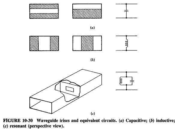
The various irises (also called waveguide apertures or diaphragms) of Figure 10-30 are a class of such obstacles. They may take any of the forms shown (or other similar ones) and may be capacitive, inductive or resonant. The mathematical analysis is complex, but fortunately the physical explanation is not. Consider the first capacitive iris of Figure 10-30a. It is seen that potential which existed between the top and bottom walls of the waveguide (in the dominant mode) now exists between surfaces that are closer, and therefore capacitance has increased at that point. Conversely, the iris in Figure 10-30b allows current to flow where none flowed before. The electric field that previously advanced now has a metal surface in its plane, which permits current flow. Energy storage in the magnetic field thus takes place, and there is an increase in inductance at that point of the waveguide.
If the iris of Figure 10-30c is correctly shaped and positioned, the inductive and capacitive reactances introduced will be equal, and the aperture will be parallel-resonant. This means that the Impedance Matching and Tuning will be very high for the dominant mode, and the shunting effect for this mode will be negligible. However, other modes or frequencies will be attenuated, so that the resonant iris acts as both a bandpass filter and a mode filter. Because irises are by their nature difficult to adjust, they are normally used to correct permanent mismatches.
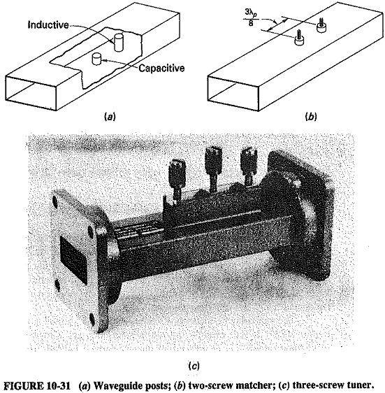
A cylindrical post, extending into the waveguide from one of the broad sides, has the same effect as an iris in providing lumped reactance at that point. A post may also be capacitive or inductive, depending on how far it extends into the waveguide, and each type is shown in Figure 10-31a.
The reasons for the behavior of such posts are complex, but the behavior itself is straightforward. When such a post extends slightly into the waveguide, a capacitive susceptance is provided at that point and increases until the penetration is approximately a quarter-wavelength, at which point series resonance occurs. Further insertion of the post results in the providing of an inductive susceptance, which decreases as insertion is more complete. The resonance at the midpoint insertion has a sharpness that is inversely proportional to the diameter of the post, which can once again be employed as a filter, However, this time it is used as a band-stop filter, perhaps to allow the propagation of a higher mode in a purer form.
The big advantage which the post has over the iris is that it is readily adjustable, A combination of two such posts in close proximity, now called screws and shown in Figure 10-3 lb, is often used as a very effective waveguide matcher, similar to the double-stub tuner (Figure 7-18). A three-screw tuner, as shown in Figure 10-Me, may also be used, to provide even greater versatility.
Finally, it will be remembered that an E-plane tee may also be used in a manner identical to an adjustable transmission-line stub, when it is provided with a sliding, short-circuiting piston. Two such tees in close proximity are then analogous to a double-stub matcher.
Resistive Loads and Attenuators:
Waveguides, like any other transmission system, sometimes require perfectly Impedance Matching and Tuning loads, which absorb incoming waves completely without reflections, and which are not frequency-sensitive. One application for such terminations is in making various power measurements on a system without actually radiating any power.
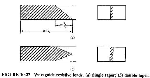
The most common resistive termination is a length of lossy dielectric fitted in at the end of the waveguide and tapered very gradually (with the sharp end pointed at the incoming wave) so as not to cause reflections. Such a lossy vane may occupy the whole width of the waveguide, or perhaps just the center of the waveguide end, as shown in Figure 10-32. The taper may be single or double, as illustrated, often having a length of λp/2, with an overall vane length of about two wavelengths. It is often made of a dielectric slab such as glass, with an outside coating of carbon film or aquadag. For high-power applications, such a termination may have radiating fins external to the waveguide, through which power applied to the termination may be dissipated or conducted away by forced-air cooling.
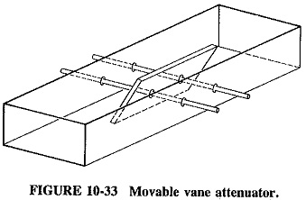
The vane may be made movable and used as a variable attenuator, as shown in Figure 10-33. It will now be tapered at both ends and situated in the middle of a waveguide rather than at the end. It may be moved laterally from the center of the waveguide, where it will provide maximum attenuation, to the edges, where attenuation is considerably reduced because the electric field intensity there is much lower for the dominant mode. To minimize reflections from the mounting rods, they are made perpendicular to the electric field, as shown, and placed λp/2 apart so that reflections from one will tend to cancel those from the other.
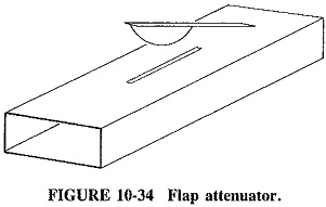
The flap attenuator, shown in Figure 10-34, is also adjustable and may be employed instead of the moving vane attenuator. A resistive element is mounted on a hinged arm, allowing it to descend into the center of the waveguide through a suitable longitudinal slot The support for the flap attenuator is simpler than for the vane. The depth of insertion governs the attenuation, and the dielectric may be shaped to make the attenuation vary linearly with depth of insertion.
This type of attenuator is quite often used in practice, especially in situations where a little radiation from the slot is not considered significant. Both vanes and flaps are capable of attenuations in excess of 80 dB.
Attenuation in waveguides:
Waveguides below cutoff have attenuation for any or all of the following causes:
- Reflections from obstacles, discontinuities or misaligned waveguide sections
- Losses due to currents flowing in the waveguide walls
- Losses in the dielectric filling the waveguide
The last two are similar to, but significantly less than, the corresponding losses in coaxial lines. They are lumped together and quoted in decibels per 100 meters. Such losses depend on the wall material and its roughness, the dielectric used and the frequency (because of the skin effect). Typical losses for standard, rigid air-filtered rectangular waveguides are shown in Table 10-1. For brass guides they range from 4 dB/ 100 m at 5 GHz, to 12 dB/100 m at 10 GHz, although for aluminum guides they are somewhat lower. For silver-plated waveguides, losses are typically 8 dB/100 m at 35 GHz, 30 dB/100 m at 70 GHz and nearly 500 dB/100 m at 200 GHz. To reduce losses, especially at the highest frequencies, waveguides are sometimes plated (on the inside) with gold or platinum.
As already pointed out, the waveguide behaves as a high-pass filter. There is heavy attenuation for frequencies below cutoff, although the waveguide itself is virtually lossless. Such attenuation is due to reflections at the mouth of the guide instead of propagation. Some propagation does take place in so-called evanescent modes, but this is very slight.
For a waveguide operated well below cutoff, it may be shown that the attenuation A is given by
![]()
and
![]()
Under these conditions, attenuation is substantially independent of frequency and reduces to
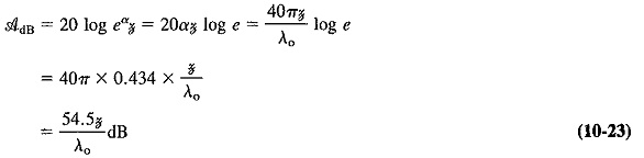
where AdB is the ratio, expressed in decibels, of the input voltage to the output voltage from a waveguide operated substantially below cutoff.
A waveguide below cutoff is often used as an adjustable, calibrated attenuator for UHF and microwave applications. Such a piston attenuator is a piece of waveguide to which the output of the generator is connected and within which a coaxial line may slide. The line is terminated in a probe or loop, and the distance between this coupling element and the generator end of the waveguide may be varied, adjusting the length of the waveguide and therefore its attenuation.