Waveguide Coupling:
When waveguide pieces or components are joined together, the Waveguide Coupling is generally by means of some sort of flange. The function of such a flange is to ensure a smooth mechanical junction and suitable electrical characteristics, particularly low external radiation and low internal reflections. The same considerations apply to a rotating coupling, except that the mechanical construction of it is more complicated.
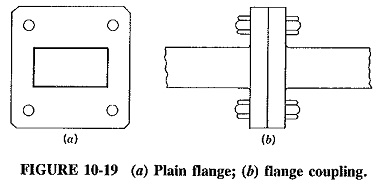
Flanges:
A typical piece of waveguide will have a flange at either end, such as illustrated in Figure 10-19. At lower frequencies the flange will be brazed or soldered onto the waveguide, whereas at higher frequencies a much flatter butted plain flange is used. When two pieces are joined, the flanges are bolted together, care being taken to ensure perfect mechanical alignment if adjustment is provided. This prevents an unwanted bend or step, either of which would produce undesirable reflections. It follows that the guide ends and flanges must be smoothly finished to avoid discontinuities at the junction.
It is obviously easier to align individual pieces correctly if there is some adjustment, so that waveguides with smaller dimensions are sometimes provided with threaded flanges, which can be screwed together with ring nuts.
With Waveguide Coupling naturally reduced in size when frequencies are raised, a coupling discontinuity becomes larger in proportion to the signal wavelength and the guide dimensions. Thus discontinuities at higher frequencies become more troublesome. To counteract this, a small gap may be purposely left between the waveguides, as shown in Figure 10-20. The diagram shows a choke coupling consisting of an ordinary flange and a choke flange connected together. To compensate for the discontinuity which would otherwise be present, a circular choke ring of L cross section is used in the choke flange, in order to reflect a short circuit at the junction of the waveguides. This is possible because the total length of the ring cross section, as shown, is λp/2, and the far end is short-circuited. Thus an electrical short circuit is placed at a surface where a mechanical short circuit would be difficult to achieve.
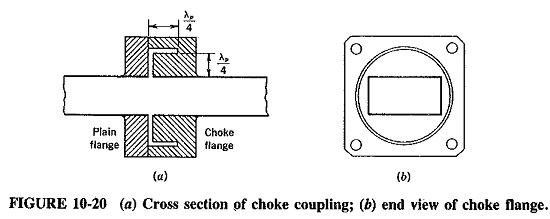
Unlike the plain flange, the choke flange is frequency-sensitive, but optimum design can ensure a reasonable bandwidth (perhaps 10 percent of the center frequency) over which SWR does not exceed 1.05.
Rotating Couplings:
As previously mentioned, rotating couplings are often used, as in radar, where a waveguide is connected to a horn antenna feeding a paraboloid reflector which must rotate for tracking. A rotating coupling involving circular waveguides is the most common and will be the one described here.
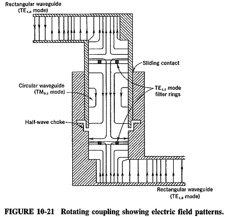
A typical rotary coupling is shown in Figure 10-21, which (for simplicity) shows the electrical components only. The mechanical components may have varying degrees of complexity but are of subsidiary interest here. The rotating part of the waveguide is circular and carries the TM0,1 mode, whereas the rectangular waveguide pieces leading in and out of the coupling carry the dominant TE1,0 mode. The circular Waveguide Coupling has a diameter which ensures that modes higher than the TM0,1 cannot propagate. The dominant TE1,1 mode in the circular guide is suppressed by a ring filter, which tends to short-circuit the electric field for that mode, while not affecting the electric field of the TM0,1 mode (which is everywhere perpendicular to the ring). A choke gap is left around the circular guide coupling to reduce, any mismatch that may occur and any rubbing of the metal area during the rotation. Some sort of obstacle is often placed at each circular-rectangular waveguide junction to compensate for reflection.
Basic Accessories:
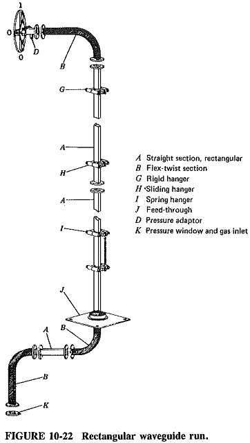
A manufacturer’s catalog shows a very large number of accessories which can be obtained with Waveguide Coupling for any number of purposes. Figure 10-22 shows a typical rectangular waveguide run which illustrates a number of such accessories; some of them are now described.
Bends and corners:
As indicated in Figure 10-22, changes of direction are often required, in which case a bend or a corner may be used. Since these are discontinuities, SWR will be increased either because of reflections from a corner, or because of a different group velocity in a piece of bent Waveguide Coupling.
An H-plane bend (shown in Figure 10-22a) is a piece of waveguide smoothly bent in a plane parallel to the magnetic field for the dominant mode (hence the name). In order to keep the reflections in the bend small, its length is made several wavelengths. If this is undesirable because of size, or if the bend must be sharp, it is possible to minimize reflections by making the mean length of the bend an integral number of guide wavelengths. In that case some cancellation of reflections takes place. It must be noted that the sharper the bend, the greater the mismatch introduced.
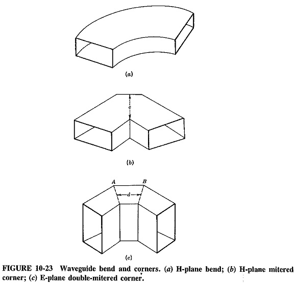
For the larger wavelengths a bend is rather clumsy, and a corner may be used instead. Because such a corner would introduce intolerable reflections if it were simply a 90° corner, a part of it is cut, and the corner is then said to be mitered, as in Figure 10-23b. The dimension c depends on wavelength, but if it is correctly chosen, reflections will be almost completely eliminated. An H-plane corner is shown. With an E-plane corner, there is a risk of voltage breakdown across the distance c, which would naturally be fairly small in such a corner. Thus if a change of direction in the E plane is required, a double-mitered corner is used (as in Figure 10-23c). In this both the inside and outside corner surfaces are cut, and the thickness of the corner is the same as that of the straight portion of Waveguide Coupling. If the dimension d is made a quarter of a guide wavelength, reflections from corners A and B will cancel out, but that, in turn, makes the corner frequency-sensitive.
Taper and twist sections:
When it is necessary to Waveguide Coupling having different dimensions or different cross-sectional shapes, taper sections may be used. Again, some reflections will take place, but they can be reduced if the taper section is made gradual, as shown for the circular-rectangular taper of Figure 10-24a. The taper shown may have a length of two or more wavelengths, and if the rectangular section carries the dominant mode, the TE1,1 mode will be set up in the circular section. and vice versa.
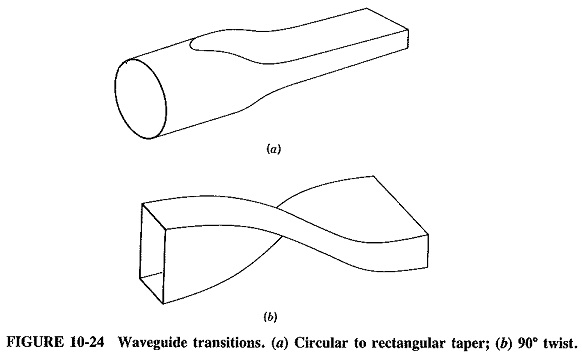
Finally, if a change of polarization direction is required, a twist section may be used (as shown in Figure 10-24b), once again extending over two or more wavelengths. As an alternative, such a twist may be incorporated in a bend, such as those shown in Figure 10-22..