Waveguide Isolator and Circulators:
It often happens at microwave frequencies that coupling must be strictly a one-way affair. This applies for most microwave generators, whose output amplitude and frequency could be affected by changes in load impedance. Some means must be found to ensure that the coupling is unidirectional from generator to load. A number of semiconductor devices used for microwave amplification and oscillation are two-terminal devices, in which the input and output would interfere unless some means of isolation were found. As a result, devices such as Waveguide Isolator and Circulators are frequently employed. They have properties much the same as directional couplers and hybrid junctions, respectively, but with different applications and construction. Since various ferrites are often used in Waveguide Isolator and Circulators, these materials must be studied before the devices themselves.
Introduction to ferrites:
A ferrite is a nonmetallic material (though often an iron oxide compound) which is an insulator, but with magnetic properties similar to those of ferrous metals. Among the more common ferrites are manganese ferrite (MnFe2O3), zinc ferrite (ZnFe2O3) and associated ferromagnetic oxides such as yttrium-iron-garnet [Y3Fe2(FeO4)3], or YIG for short. (Gamets are vitreous mineral substances of various colors and composition, several of them being quite valuable as gems.) Since all these materials are insulators, electromagnetic waves can propagate in them. Because the ferrites have strong magnetic properties, external magnetic fields can be applied to them with several interesting results, including the Faraday rotation mentioned in connection with wave propagation.
When electromagnetic waves travel through a ferrite, they produce an RF magnetic field in the material, at right angles to the direction of propagation if the mode of propagation is correctly chosen. If an axial magnetic field from a permanent magnet is applied as well, a complex interaction takes place in the ferrite. The situation may be somewhat simplified if weak and strong interactions are considered separately.
With only the axial dc magnetic field present, the spin axes of the spinning electrons align themselves along the lines of magnetic force, just as a magnetized needle aligns itself with the earth’s magnetic field. Electrons spin because this is a magnetic material. In other materials spin is said to take place also, but each pair of electrons has individual members spinning in opposite directions, so that there is an overall cancellation of spin momentum. The so-called unpaired spin of electrons in a ferrite causes individual electrons to have angular momentum and a magnetic moment along the axis of spin. Each electron behaves very much like a gyroscope. This is shown in Figure 10-39a.
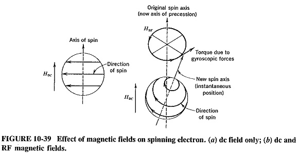
When the RF magnetic field due to the propagating electromagnetic waves is also applied, it is perpendicular to the axial dc magnetic field, so that the electrons precess about their original spin axis. This is due to the gyroscope forces involved and occurs at a rate that depends on the strength of the dc magnetic field. Furthermore, it is identical to the behavior that an ordinary gyroscope would exhibit under these conditions. Because of the precession, a magnetic component at right angles to the other two is produced, as shown in Figure 10-39b. This has the effect of rotating the plane of polarization of the waves propagating through the ferrite and is similar to the behavior of light, which Michael Faraday discovered in 1845.
The amount by which the plane of polarization of the waves will be rotated depends on the length and thickness of the ferrite material, and on the strength of the dc magnetic field. The field must provide at least saturation magnetization, which is the minimum value required to ensure that the axes of the spinning electrons are suitably aligned. In turn, this is tied up in a rather complex fashion with the lowest usable frequency of the ferrite. This property of ferrites, whereby the plane of polarization of propagating waves is rotated, is a basis for a number of nonreciprocal devices. These are devices in which the properties in one direction differ from those in the other direction. Metallic magnetic materials cannot be used for such applications because they are conductors. Thus electromagnetic waves cannot propagate in them, whereas they can in ferrites, with relatively low losses.
The rate of precession is proportional to the strength of the dc magnetic field and is 3.52 MHz per ampere per meter for most ferrites. For example, if this field is 1000 A/m, the frequency of precession will be 3.52 GHz. Such a magnetic field strength is well above saturation and therefore higher than would be used if merely a rotation of the plane of polarization were required. If the dc magnetic field is made as strong as this or even stronger, the possibility of the precessional frequency being equal to the frequency of the propagated electromagnetic waves is introduced. When this happens, gyromagnetic resonance interaction takes place between the spinning electrons and the magnetic field of the propagating waves. If both the electrons and this magnetic field are rotating clockwise, energy is delivered to the electrons, making them rotate more violently. Absorption of energy from the magnetic field of the propagating waves thus takes place, and the energy is dissipated as heat in the crystalline structure of the ferrite material. If the two spins are in the opposite sense, energy is alternately exchanged between the electrons and the RF magnetic field. Since the net effect is zero, the electromagnetic propagating waves are unaffected. This behavior also forms the basis for devices with nonreciprocal properties.
Two other quantities of importance must now be mentioned. The first is line width, which is the range of magnetic field strengths over which absorption will take place and is defined between the half-power points for absorption. A wide line indicates that the material has wideband properties, and materials can be modified to possess it, but generally at the expense of other properties. YIG has the narrowest line width known, corresponding to Q’s over 10,000. The other quantity is the Curie temperature, at which a magnetic material loses its magnetic properties. It ranges up to 600°C for ferrites but may be as low as 100°C for materials with special properties such as broad line width. It is 280°C for YIG. This places a limitation on the maximum temperature at which a ferrite may be operated, and therefore on the power dissipated.
However, with external cooling, ferrite devices are available that can handle powers as high as 150 kW CW and 3 MW pulsed.
The final limitation to which ferrites may be subject is their maximum frequency of operation. For a device utilizing resonance absorption, this is dependent on the maximum magnetic field strength that can be generated and is offset somewhat by the general reduction in the size of waveguides as frequency is increased. The present upper frequency limit for commercial devices is in excess of 220 GHz.
Isolators:
Ferrite isolators may be based either on Faraday rotation, which is used for powers up to a few hundred watts, or on resonant absorption, used for higher powers. The Faraday rotation isolator, shown in Figure 10-40, will be dealt with first.
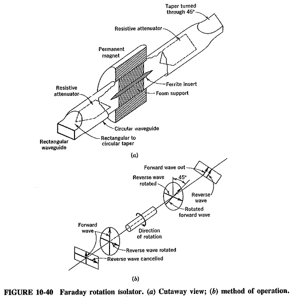
The isolator consists of a piece of circular waveguide carrying the TE1,1 mode, with transitions to a standard rectangular guide and TE1,0 mode at both ends (the output end transition being twisted through 45°). A thin “pencil” of ferrite is located inside the circular guide, supported by polyfoam, and the waveguide is surrounded by a permanent magnet which generates a magnetic field in the ferrite that is generally about 160 A/m. A typical practical X-band (8.0 to 12.4 GHz) device may have a length of 25 mm and a weight of 100 g without the transitions.
Because the dc magnetic field (well below that required for resonance) is applied, a wave passing through the ferrite in the forward direction will have its plane of polarization shifted clockwise (through 45° in practical Waveguide Isolator and Circulators) by the time it reaches the output end. This wave is then passed through the suitably rotated output transition, and it emerges with an insertion loss (attenuation in the forward direction) between 0.5 and 1 dB in practice. It has not been affected by either of the resistive vanes because they are at right angles to the plane of its electric field; this is shown in Figure 10-40b.
A wave that tries to propagate through the isolator in the reverse direction is also rotated clockwise, because the direction of the Faraday rotation depends only on the dc magnetic field. Thus, when the wave emerges into the input transition, not only is it absorbed by the resistive vane, but also it cannot propagate in the input rectangular waveguide because of its dimensions. This situation is shown in Figure 10-40b. It results in the returned wave being attenuated by 20 to 30 dB in practice (this reverse attenuation of an isolator is called its isolation). Such a practical Waveguide Isolator and Circulators will have an SWR not exceeding 1.4, with values as low as 1.1, which is sometimes obtainable, and a bandwidth between 5 and 30 percent of the center frequency.
This type of isolator is limited in its peak power-handling ability to about 2 kW, , because of nonlinearities in the ferrite resulting in the phase shift departing from the ideal 45°. However, it has a very wide range of applications in the low-power field, since most microwave amplifiers and oscillators have output powers considerably lower than 2 kW.
The other popular type of Waveguide Isolator and Circulators is the resonant absorption isolator, which is commonly used for high powers. It consists of a piece of rectangular waveguide carrying the TE1,0 mode, with a piece of longitudinal ferrite material placed about a quarter of the way from one side of the waveguide and halfway between its ends. A permanent magnet is placed around it and generates a much stronger field than in the Faraday rotation isolator. The arrangement of the resonant absorption isolator is shown schematically in Figure 10.41.
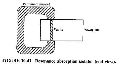
Examination of the field patterns for the TE1,0 mode in rectangular waveguides shows that the ferrite has been placed at a point where the magnetic field is strong and circularly polarized. This polarization will be clockwise in one direction of propagation, and counterclockwise in the other. There will thus be unaffected propagation in one direction but resonance (and hence absorption) if waves try to propagate in the other direction. Once again unidirectional characteristics have been achieved.
The maximum power-handling ability of resonance isolators is limited by temperature rise, which might bring the ferrite close to its Curie point. The one described and shown in Figure 10-41 is a typical medium-power resonance isolator, weighing about 300 g. It can handle up to 100 W average and 10 kW peak in the X band, having an SWR of 1.15. The isolation is typically 60 dB, and the insertion loss 1 dB. When this type of Waveguide Isolator and Circulators is modified, it can handle powers in excess of 300 kW pulsed in the X band, and much more at lower microwave frequencies.
Circulators:
A circulator is a ferrite device somewhat like a rat race. It is very often a four-port (i.e., four-terminal) device, as shown in Figure 10-42a, although other forms also exist. It has the property that each terminal is connected only to the next clockwise terminal. Thus port 1 is connected to port 2, but not to 3 or 4; 2 is connected to 3, but not to 4 or 1; and so on. The main applications of such circulators are either the isolation of transmitters and receivers connected to the same antenna (as in radar), or isolation of input and output in two-terminal amplifying devices such as parametric amplifiers.
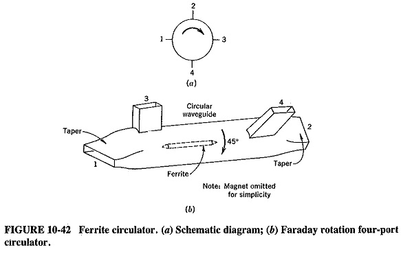
A four-port Faraday rotation circulator is shown in Figure 10-42. It is similar to the Faraday rotation isolator already described. Power entering port 1 is converted to the TE1,1 mode in the circular waveguide, passes port 3 unaffected because the electric field is not significantly cut, is rotated through 45° by the ferrite insert (the magnet is omitted for simplicity), continues past port 4 for the same reason that it passed port 3, and finally emerges from port 2, just as it did in the isolator. Power fed to port 2 will undergo the same fate that it did in the isolator, but now it is rotated so that although it still cannot come out of port 1, it has port 3 suitably aligned and emerges from it. Similarly, port 3 is coupled only to port 4, and port 4 to port 1. This type of circulator is power-limited to the same extent as the Faraday rotation isolator, but it is eminently suitable as a low-power device. However, since it is bulkier than the Y (or wye) circulator (to be described), its use is restricted mostly to the highest frequencies, in the millimeter range and above. Its characteristics are similar to those of the isolator.
High-power circulators are fairly similar to the resonance isolator and handle powers up to 30 MW peak.
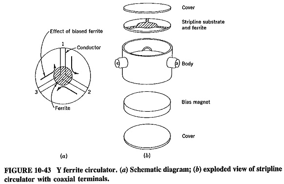
Figure 10-43 shows a miniature Y (or wye) circulator. There are waveguide, coaxial, and stripline versions of it. A three-port version is shown—a four-port circulator of this type is obtained by joining two wyes together. This is seen in Figure 10-50, in a slightly different context.
With the magnet on one side of the ferrite only, and with a suitable magnetic field strength, a phase shift will be applied to any signal fed in to the circulator. If the three striplines and coaxial lines are arranged 120° apart as shown, a clockwise shift and correct terminations will ensure that each signal is rotated so as to emerge from the next clockwise port, without being coupled to the remaining port. In this fashion, circulator properties are obtained. A practical Y circulator of the type shown is typically 12 mm high and 25 mm in diameter. It handles only small powers but may have an isolation over 20 dB, an insertion loss under 0.5 dB and an SWR of 1.2, all in the X band. A similar four-port circulator, consisting of two joined wyes, will be housed in a rectangular box measuring 45 x 25 x 12 mm. It will have similar performance figures, except that the isolation is now in excess of 40 dB, and the insertion loss is about 0.9 dB.