What is Frequency Response of an Amplifier?
The voltage gain of an amplifier varies with signal frequency due to the effect of variations in circuit capacitive reactance with signal frequency on the output voltage. The curve drawn between the voltage gain and signal frequency of an amplifier is known as the frequency response.
If the input voltage of an amplifier is kept constant but its frequency is varied, it is observed that the amplifier gain
- remains practically constant over a sizeable range of mid frequencies.
- falls off at low as well as high frequencies, due to effects explained below:
The performance of an amplifier depends to a considerable extent upon its frequency response. In the design of an ac amplifier, appropriate steps are taken to ensure that gain is essentially uniform over some specified frequency range.
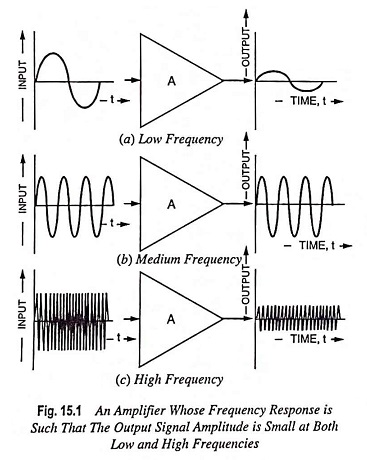
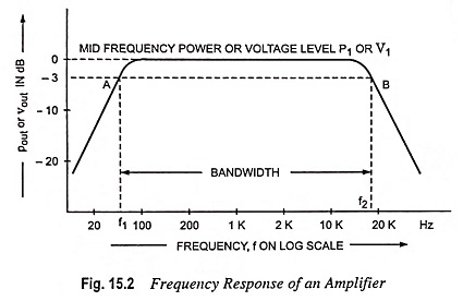
A typical graph of an ac amplifier output voltage or power plotted versus frequency is shown in Fig. 15.1. It is found that the output normally remains constant over a middle range of frequencies and falls off at low and high frequencies. The gain over this middle range is termed the mid frequency gain. The low frequency and high frequency at which gain falls by 3 dB are designated f1 and f2 respectively. This range is normally considered the useful range of operating Frequency Response of an Amplifier, and the frequency difference (f2 – f1) is termed the amplifier bandwidth.
Frequencies f1 and f2 are referred to as -3 dB frequencies, down 3 dB frequencies or 3 dB loss frequencies because the power output is – 3 dB from its normal level when P2 is half of P1. The points A and B in Fig. 15.2 are called 3 dB (sometimes -3 dB) or half-power points. When the amplifier output is expressed as a voltage on the graph of Frequency Response of an Amplifier, the 3 dB points (f1 and f2) occur when V2 is 0.707 V1.
At low frequencies, the voltage gains fall because the coupling and bypass capacitors no longer act like short circuits. Instead, their capacitive reactances are large enough to drop some of the ac signal voltage. The result is a loss of voltage gain as we approach zero hertz (0 Hz).
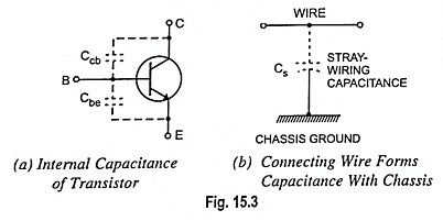
At high frequencies, the voltage gain falls for other reasons. All transistors have capacitances between their terminals, known as internal capacitances, as illustrated in Fig. 15.3 (a). These capacitances provide bypass path for the ac signal. With the increase in frequency, capacitive reactances become low enough (XC α 1/f) to prevent normal transistor action. The result is a loss of voltage gain.
Stray-wiring capacitance is another reason for a loss of voltage gain at high frequencies [Fig. 15.3 (b)]. Any connecting wire in a transistor circuit acts like one plate of a capacitor, and the chassis ground acts like the other plate. The stray-wiring capacitance that exists between this wire and ground is unwanted. At higher frequencies, its low capacitive reactance prevents the ac current from reaching the load resistor. This is equivalent to saying that the voltage gain drops off.
Equivalent Circuits of Frequency Response of an Amplifier:
Each capacitor in a circuit is important to only one end of the frequency spectrum. That is why, we can develop specific equivalent circuits that apply to low-frequency range, to midband, and to the high-frequency range.
The equivalent circuits used for calculations in the midband range are the same as those considered up to this point in the text. The coupling and bypass capacitors in this region are treated as short circuits. The stray and transistor internal capacitances are treated as open circuits. In this frequency range, there are no capacitances in the equivalent circuit. These circuits are referred to as midband equivalent circuits.
In the low frequency range, coupling and bypass capacitors are included in the equivalent circuits and in the amplification factor equations. The stray and transistor capacitances are treated as open circuits. The mathematical expressions obtained for the amplification factor in this frequency range must approach the midband results as frequency f approaches the midband frequency range, since in this limit the capacitors approach short-circuit conditions.
In the high frequency range, coupling and bypass capacitors are treated as short circuits. The transistor and any parasitic or load capacitances must be taken into account in the equivalent circuit. The mathematical expressions obtained for amplification factor in this frequency range must approach the midband results as frequency f approaches the midband frequency range, since in this limit the capacitors approach open-circuit conditions.
Cutoff Frequencies and Midband:
The frequencies at which the voltage gain equals 0.707 of its maximum value are known as the cutoff frequencies. In Fig. 15.2, f1 is the lower cutoff frequency and f2 is the upper cutoff frequency. The cutoff frequencies are also referred to as the half-power frequencies because the load power is half of its maximum value at these frequencies.
The midband of an amplifier is defined as the band of frequencies between 10f1 and 0.1f2. In the midband, the amplifier voltage gain is approximately maximum, designated by Avm. Three important characteristics of any ac amplifier are its Avm,f1 and f2. If these values are known, we know how much voltage gain there is in the midband and where the voltage gain is down to 0.707 Avm.
Outside The Midband:
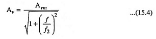
Although an amplifier normally operates in the midband frequency range, but sometimes we are to know the voltage gain outside the midband. Voltage gain (approximate value) of an ac amplifier can be computed from the relation.
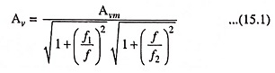
Knowing the values of Avm,f1 and f2, the voltage gain at any frequency f can be determined. The above equation assumes that one dominant capacitor is producing the lower cutoff frequency, and one dominant capacitor is producing the upper cutoff frequency. A dominant capacitor is one that is more important than all others in determining the cutoff frequency.
Equation (15.1) is not as formidable as it first appears. There are only three frequency ranges to analyze: the midband, below midband, and above midband. In the midband f1/f ≈ 0 and f/f2 ≈ 0. Therefore, both radicals in Eq. (15.1) are approximately unity, and Eq. (15.1) simplifies to :
Midband :
![]()
Below the midband, f/f2 ≈ 0. Consequently, the second radical equals 1 and Eq. (15.1) simplifies to:
Below Midband :
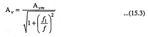
Above midband, f1/f ≈ 0. Consequently, the first radical equals 1 and Eq. (15.1) simplifies to :
Above Midband :