Intermediate Frequency Amplifier:
Choice of frequency: The Intermediate Frequency Amplifier (IF) of a receiving system is usually a compromise, since there are reasons why it should be neither low nor high, nor in a certain range between the two.
The following are the major factors influencing the choice of the Intermediate Frequency Amplifier in any particular system:
- If the Intermediate Frequency Amplifier is too high, poor selectivity and poor adjacent-channel rejection result unless sharp cutoff (e.g., crystal or mechanical) filters are used in the IF stages.
- A high value of intermediate frequency increases tracking difficulties.
- As the intermediate frequency is lowered, image-frequency rejection becomes Equations (6-1), (6-2) and (6-3) showed that rejection is improved as the ratio of image frequency to signal frequency is increased, and this requires a high IF. It is seen that image-frequency rejection becomes worse as signal frequency is raised, as was shown by Example 6-1a and b.
- A very low Intermediate Frequency Amplifier can make the selectivity too sharp, cutting off the sidebands. This problem arises because the Q must be low when the IF is low, unless crystal or mechanical filters are used, and therefore the gain per stage is A designer is more likely to raise the Q than to increase the number of IF amplifiers.
- If the IF is very low, the frequency stability of the local oscillator must be made correspondingly higher because any frequency drift is now a larger proportion of the low IF than of a high IF.
- The Intermediate Frequency Amplifier must not fall within the tuning range of the receiver, or else instability will occur and heterodyne whistles will be heard, making it impossible to tune to the frequency band immediately adjacent to the intermediate
Frequencies used: As a result of many years experience, the previous requirements have been translated into specific frequencies, whose use is fairly well standardized throughout the world (but by no means compulsory). These are as follows:
- Standard broadcast AM receivers [tuning to 540 to 1650 kHz, perhaps 6 to 18 MHz, and possibly even the European long-wave band (150 to 350 kHz)] use an IF within the 438- to 465-kHz range, with 455 kHz by far the most popular
- AM, SSB and other receivers employed for shortwave or VHF reception have a first IF often in the range from about 1.6 to 2.3 MHz, or else above 30 MHz. (Such receivers have two or more different Intermediate Frequency Amplifier.)
- FM receivers using the standard 88- to 108-MHz band have an IF which is almost always 10.7 MHz.
- Television receivers in the VHF band (54 to 223 MHz) and in the UHF band (470 to 940 MHz) use an IF between 26 and 46 MHz, with approximately 36 and 46 MHz the two most popular values.
- Microwave and radar receivers, operating on frequencies in the 1- to 10-GHz range, use intermediate frequencies depending on the application, with 30, 60 and 70 MHz among the most popular.
By and large, services covering a wide frequency range have IFs somewhat below the lowest receiving frequency, whereas other services, especially fixed-frequency microwave ones, may use Intermediate Frequency Amplifier as much as 40 times lower than the receiving frequency.
Intermediate Frequency Amplifier:
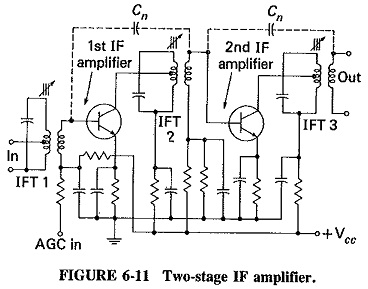
The IF amplifier is a fixed-frequency amplifier, with the very important function of rejecting adjacent unwanted frequencies. It should have a frequency response with steep skirts. When the desire for a flat-topped response is added, the resulting recipe is for a double-tuned or stagger-tuned amplifier. Whereas FET and integrated circuit IF amplifiers generally are (and vacuum-tube ones always were) double-tuned at the input and at the output, bipolar transistor amplifiers often are single-tuned. A typical bipolar IF amplifier for a domestic receiver is shown in Figure 6-11. It is seen to be a two-stage amplifier, with all IF transformers single tuned. This departure from a single-stage, double-tuned amplifier is for the sake of extra gain, and receiver sensitivity.
Although a double-tuned circuit, such as those shown in Figures 6-12 and 6-13, rejects adjacent frequencies far better than a single-tuned circuit, bipolar transistor amplifiers, on the whole, use single-tuned circuits for interstage coupling. The reason is that greater gain is achieved in this way because of the need for tapping coils in tuned circuits. This tapping may be required to obtain maximum power transfer and a reduction of tuned circuit loading by the transistor. Since transistor impedances may be low, tapping is employed, together with somewhat lower inductances than would have been used with tube circuits. If a double-tuned transformer were used, both sides of it might have to be tapped, rather than just one side as with a single-tuned transformer. Thus a reduction in gain would result. Note also that neutralization may have to be used (capacitors Cn in Figure 6-11) in the transistor IF amplifier, depending on the frequency and the type of transistor employed.
When double tuning is used, the coefficient of coupling varies from 0.8 times critical to critical, overcoupling is not normally used without a special reason. Finally, the IF transformers are often all made identical so as to be interchangeable.