Audio Power Amplifier using IC Amplifier Driver:
The LM391 integrated circuit Audio Power Amplifier using IC Amplifier Driver contains amplification and driver stages for controlling an externally-connected Class-AB output stage delivering 10 W to 100 W. The voltage gain and bandwidth are set by additional components. Internal circuitry is included for overload and thermal protection, and for protection of the (externally-connected) amplifier output transistors. The circuit is designed for very low distortion, so that it can be used for high-fidelity amplifiers. Figure 18-54 illustrates the use of the device in an audio amplifier.
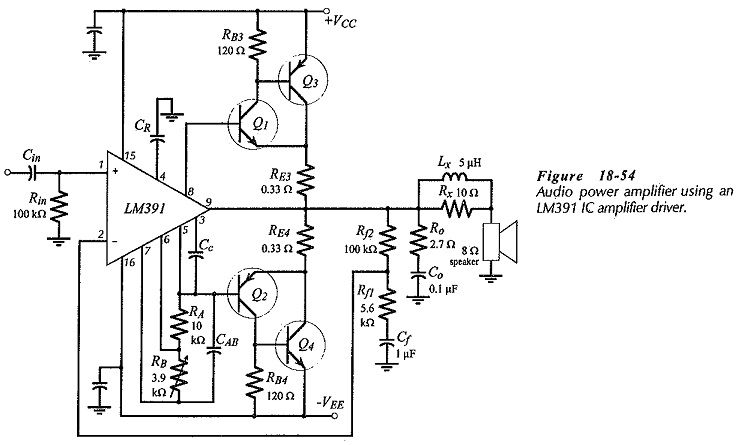
The output stage in Fig. 18-54 is seen to be a complementary emitter follower with the low power and high power transistor pairs connected in quasi-complementary form. The IC output at terminal 9 is connected to the amplifier output, and the output stage transistors are controlled from current source terminal 8 and current sink terminal 5. The circuit uses a plus-minus supply, and the noninverting input terminal of the IC is biased to ground. The inverting input terminal receives feedback from the output, so that the complete circuit operates as a non-inverting amplifier.
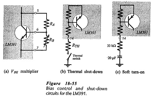
Resistors RA and RB are connected to an internal transistor (via terminals 5, 6, and 7) to constitute a VBE multiplier for controlling the bias voltage to the amplifier output stage, [see Fig. 18-55(a)]. Capacitor CAB by-passes the VBE multiplier circuit to improve the amplifier high frequency response. Capacitor CR helps to reject power supply ripple, and CC is a compensation capacitor for frequency stability. Components Ro, Co, Lx and Rx are included for load compensation.
The LM391 has an internal transistor which can shut the circuit down when turned on by a thermal switch, [Fig. 18-55(b)]. This allows the device to be protected from overheating that might occur with an excessive load current demand. This same transistor can be employed for soft turn-on of the circuit, [Fig. 18-55(c)]. If the amplifier supply voltage is switched on at the instant that a peak input signal is applied, a high level output is passed to the speaker, causing a sharp unpleasant noise. Soft turn-on causes the output to increase slowly, thus eliminating the speaker noise. The circuit in Fig. 18-55(c) holds the amplifier in a shut-down condition until the capacitor charges
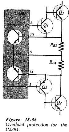
Overload protection transistors are included in the LM391, as shown in Fig. 18-56. These transistors turn on when excessive voltage drops occur across the emitter resistors (RE3 and RE4) in the output stage.
The output stage components in Fig. 18-54 are selected in the same way as for other direct-coupled Class AB amplifiers. The minimum levels of supply voltage are calculated by adding 5 V to the peak output voltage.
![]()
The input resistance at terminal 1 of the LM391 is extremely high, so the circuit input resistance is set by resistor Rin, which is typically selected as 100 kΩ. Feedback resistors Rf1 and Rf2 set the amplifier closed-loop voltage gain. The feedback network components are determined in exactly the same way as for other feedback amplifiers. Rf2 is made equal to Rin to minimize output offset, and Rf1 is calculated from Rf2 to give the desired voltage gain. Capacitor Cf is determined in terms of Rf1 to set low cut-off frequency.
250 mW IC Power Amplifier:
The LM386 is a complete power amplifier circuit capable of delivering 250 mW to an 8 Ω load without any additional components. The supply voltage range is 5 V to 18 V, and the (inverting and non-inverting) input terminals are biased to ground (or to a negative supply) via internal 50 kΩ resistors. The output is automatically centered at half the supply voltage. Feedback resistors are also provided internally to set the voltage gain at 20.
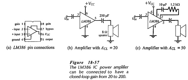
The pin connections for the LM386 are shown in Fig. 18-57(a), and the circuit connections for functioning as an amplifier with a gain of 20 is illustrated in part (b). Figure 18-57(c) shows how a capacitor and resistor can be connected at pins 1 and 8 to achieve a larger voltage gain. With the 10 μF capacitor alone, a maximum gain of 200 is obtained. The resistor in series with the capacitor allows the voltage gain to be set anywhere between 20 and 200.