Transient Response of RL Circuit:
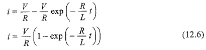
Considers a Transient Response of RL Circuit consisting of a resistance and inductance as shown in Fig. 12.1. The inductor in the circuit is initially uncharged and is in series with the resistor. When the switch S is closed, we an find the complete solution for the current. Application of Kirchhoff’s voltage law to the circuit results in the following differential equation.
![]()
or
![]()
In the above equation, the current i is the solution to be found and V is the applied constant voltage. The voltage V is applied to the circuit only when the switch S is closed. The above equation is a linear differential equation of first order. Comparing it with a non-homogeneous differential equation
![]()
whose solution is
![]()
where c is an arbitrary constant. In a similar way, we can write the current equation as
![]()
To determine the value of c in Eq. 12.5, we use the initial conditions. In the Transient Response of RL Circuit shown in Fig. 12.1, the switch S is closed at t=0. At t=0–, i.e. just before closing the switch S, the current in the inductor is zero. Since the inductor does not allow sudden changes in currents, at t=0+ just after the switch is closed, the current remains zero.
Thus at![]()
Substituting the above condition in Eq. 12.5, we have
![]()
Hence
![]()
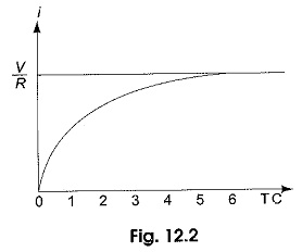
Subslituting the value of c in Eq. 5, we get
Equation 12.6 consists of two parts, the steady state part V/R, and the transient part (V/R)e-(R/L)t. When switch S is closed, the response reaches a steady state value after a time interval as shown in Fig. 12.2.
Here the transition period is defined as the time taken for the current to reach its final or steady state value from its initial value. In the transient part of the solution, the quantity L/R is important in describing the curve since L/R is the time required for the current to reach from its initial value of zero to the final value V/R. The time constant of a function V/R e-(R/L)t is the time at which the exponent of e is unity, where e is the base of the natural logarithms. The term L/R is called the time constant and is denoted by τ![]()
The transient part of the solution is
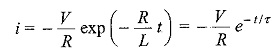
At one TC, i.e. at one time constant, the transient term reaches 36.8 percent of its initial value.
![]()
Similarly,
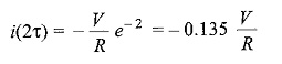
![]()
After 5 TC, the transient part reaches more than 99 percent of its final value. In Fig. 12.1, we can find out the voltages and powers across each element by using the current.
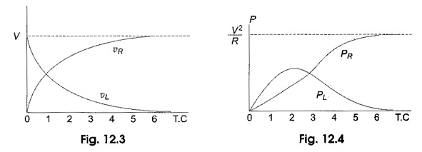
Voltage across the resistor is
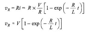
Similarly, the voltage across the inductance is
![]()
The response are shown in Fig. 12.3
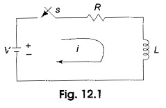
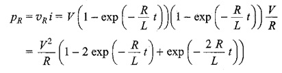
Power in the resistor is
Power in the inductor is
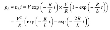
The responses are shown in Fig. 12.4.