Transient Analysis of DC Motor:
Starting, braking, reversing speed changing and load changing are the Transient Analysis of DC Motor which commonly occur in an industrial drive. One is interested in knowing how current, torque and speed of the driving motor change with time when under these transient operations. One is also interested in knowing energy losses, particularly those responsible for heating of the motor, and time taken for the completion of the Transient Analysis of DC Motor. This information is needed by the designer for selecting suitable rating of the motor, nature and type of its control equipment and its operation schedule, and types of protective devices and their settings.
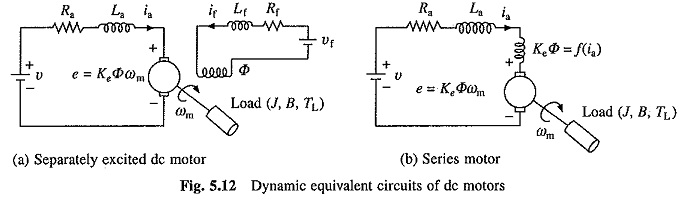
Dynamic equivalent circuits of dc motors are shown in Fig. 5.12. Source voltage v motor armature current ia and back emf e are denoted by lower case letters to emphasize that these are instantaneous values of time varying quantities. B and J are respectively the coefficient of viscous friction in Nm/rad/sec and polar moment of inertia in kg-m2 of the motor load system referred to the motor shaft.
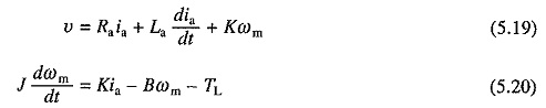
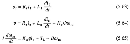
Voltage equation of the armature circuit under transient is given by
![]()
From the dynamics of motor load system
![]()
Further
![]()
The above Transient Analysis of DC Motor are valid for any dc motor. In case of a separately excited motor when field current is maintained constant, flux remains constant, and (5.16) and (5.17) are linear differential equations. In case of a series motor, due to saturation of the magnetic circuit, flux is a nonlinear function of the armature current, and therefore, (5.16) and (5.17) are nonlinear differential equations. Even if magnetic circuit is assumed linear by neglecting saturation, (5.16) and (5.17) are nonlinear differential equations due to e being proportional to the product of ia and ωm, and T being proportional to i2a. Thus, for a series motor these equations can only be solved numerically using 4th order Rungekutta method or predictor corrector method.
Transient Analysis of Separately Excited Motor with Armature Control:
When field current is kept constant, flux remains constant. Replacing KeΦ by a constant K in Eqs. (5.16) to (5.18), yields
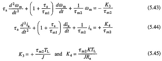
Differentiating Eq. (5.20) gives
![]()
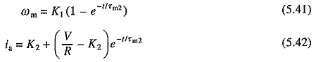
Substituting in Eq. (5.19) for dia/dt from (5.21) and rearranging terms gives

Differentiating Eq. (5.19) gives
![]()
Substituting in Eq. (5.20) for dωm/dt from Eq. (5.23) and rearranging the terms yields

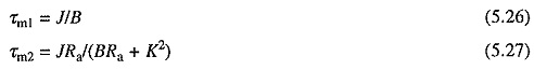
where
![]()
Equations (5.22) and (5.24) are second order linear differential equations and can be solved if the appropriate initial conditions are known. Once ia vs t relation is obtained from Eq. (5.24), T vs t relation can be calculated.
Transient Analysis of Starting of Separately Excited Motor with Armature Control:
Transient analysis of starting process will be considered here to demonstrate how the above derived equations are utilized. It will be assumed that the motor is started with a constant voltage V impressed across its terminals against a constant load torque TL and with a fixed resistance Ra in its armature circuit.
It is customary to assume that the motor starts only after its developed torque exceeds load torque. For this motor current should reach the value IL given by
![]()
When motor is connected to the supply, initial value of current is zero and due to armature circuit inductance it takes some time to reach the value IL. During whole of this period, which will be termed as first interval of the transient response, motor remains at standstill and so its back emf remains zero. Motor behaves like a simple Ra – La load. Hence its current is given by
![]()
Second interval of transient response starts after current reaches the value IL. Since V and TL are constants, dv/dt and dTL/dt will be zero. Substituting these values in Eqs. (5.22) and (5.24) gives
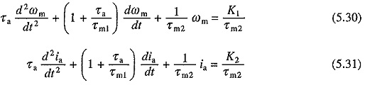
where

K1 and K2 represent the steady state values of speed and current receptively with load torque equal to TL.
Initial conditions needed for the solution of Eqs. (5.30) and (5.31) are
![]()
Since at the beginning of this interval, motor torque is equal to load torque, from Eq. (5.17)
![]()
Further from Eq. (5.16)
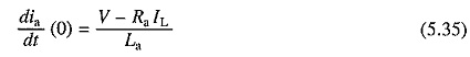
Solutions of Eqs. (5.30) and (5.31) with the initial conditions given by (5.33) to (5.35), will have the form:
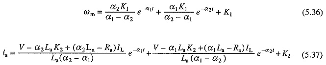
where α1 and α2 are roots of characteristic equation and are given by
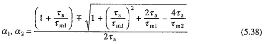
Note that the above equations have been derived by measuring time from the beginning of the second interval.
For motors less than 1000 kW, roots α1 and α2 are usually real. For larger and also for small and medium size motors with an external inductance connected in the armature circuit, as in the case of some chopper and rectifier fed Transient Analysis of DC Motor, roots can be complex. The nature of ωm vs t and ia vs t curves for starting transients, when roots are real, are shown in Fig. 5.13(a).
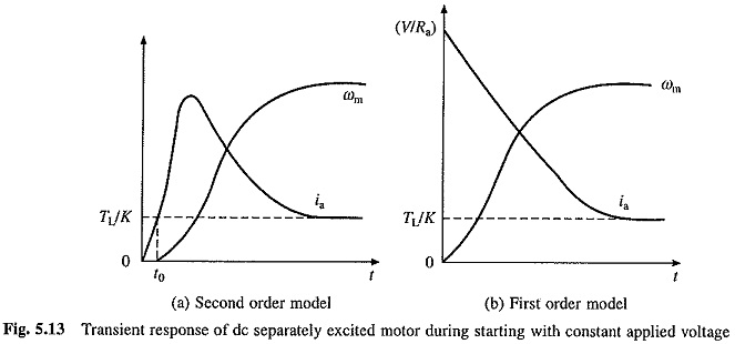
In small size motors, τa is very small due to a large armature winding resistance. It can, therefore, be neglected. Substituting τa = 0 in Eqs. (5.30) and (5.31) gives
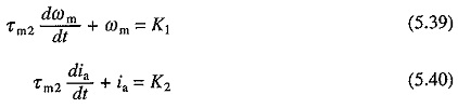
Since τa = 0, current jumps to the value V/Ra in zero time. Thus, initial conditions are
![]()
Solutions of Eqs. (5.39) and (5.40) yield
Nature of ωm versus t and ia versus t curves based on these equations are shown in Fig. 5.13(6).
Transient Analysis of Dynamic Braking of Separately Excited Motor:
It is assumed that a constant active load torque TL is acting on the motor shaft. Transient speed and current equations can be obtained by substituting new value for armature circuit resistance and V = 0 in Eqs. (5.30) and (5.31). This gives
Here also — K3 and K4 represent the steady state values of speed and current, respectively. This steady state running will occur when active load torque TL is allowed to drive the motor in reverse direction. Initial conditions needed for the solution of these equations are obtained as:
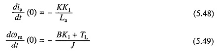
It is assumed that at the initiation of braking the motor was running in steady state with load torque TL. Then from Eq. (5.30)
![]()
For a general case K1 is to be taken as the initial speed.
Braking can be applied with or without opening the armature circuit. When it is not opened, during transition from motoring to braking, the armature current continuity will be maintained and then initial value of current, from Eq. (5.31), will be K2. However, if it is opened then the initial value of current will be zero. Here it is assumed that it is opened during transition. Therefore
![]()
Now from Eqs. (5.19) and (5.20), by substituting v = 0, ia = 0 and ωm = K1.
Solutions of Eqs. (5.43) and (5.44) with the initial conditions of (5.46) to (5.49) will have the form:
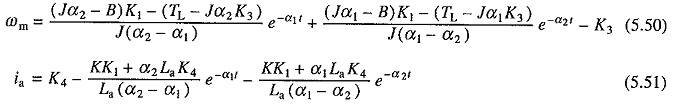
where α1 and α2 are given by Eq. (5.38).
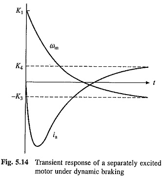
The nature of transient response under dynamic braking for the case of real α1 and α2 is shown in Fig. 5.14.
The transient equations for the plugging operation are obtained from (5.19), (5.20), (5.22) and (5.24) by substituting – v for v.
Energy Losses During Transient Operations:
Energy losses in motor and in resistors in motor armature circuit, if there are any, during transient period of operation, are required for selecting suitable ratings of motor and resistors. They are also needed to calculate the efficiency and effectiveness of the transient process.
Multiplying both sides of Eq. (5.16) by ia gives
![]()
Considering the viscous friction torque to be a part of the load torque TL, we have from Eq. (5.17)
![]()
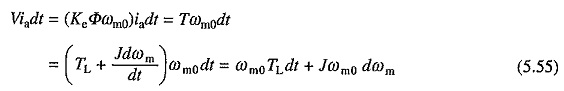
Substituting from Eqs. (5.18) and (5.53) into (5.52) and integrating both sides of the resulting equation against time yield

This equation states that out of the total energy supplied by the source during a transient process, one portion is wasted in armature circuit resistance, second portion is stored in armature circuit inductance, third portion is stored in inertia of mechanical parts and the rest is consumed by the load. Energy stored in the armature circuit inductance is usually small compared to other energy terms, and therefore, will be neglected in subsequent analysis.
Starting of the motor with a constant applied voltage V and a load torque TL is considered now.
Since
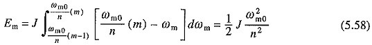
where ωm0 is the ideal no load speed. From Eqs. (5.54) and (5.55)
![]()
Equation (5.56) gives an expression for energy loss in the armature circuit resistance of the machine. When started on no load the final (steady state) speed will be ωm0. Hence, energy loss under no load condition E0 is
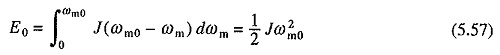
It is interesting to note that the energy loss in motor armature circuit during starting without load is equal to the kinetic energy stored in rotating parts of the motor at steady state speed. Further, it is independent of the duration of starting process, nature of speed-torque and speed-current characteristics of the motor, number of steps in starting resistance and the value of reistance in each step.
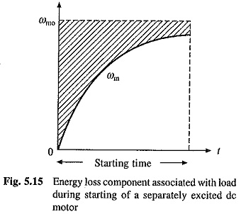
Since ωm0 will not be very much different from the steady state speed with load TL on the motor shaft, first term on R.H.S. of Eq. (5.56) approximately represents the copper loss during starting under no load and what has been said about E0 is also applicable to this term. Second term depends on load-torque, motor speed-torque characteristics and the value of starting resistance. This term is represented by the shaded area of Fig. 5.15.
As stated above first term on right side of (5.56) remains unchanged with the change of starting resistance. It can however be lowered by reduced voltage method of starting. Let us consider the case in which source voltage is applied in a number of equal steps. First part of the copper loss on mth step will be
Since this part of the copper loss will be the same on all the n steps, total no load copper loss during starting becomes
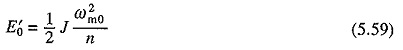
Comparison of this with Eq. (5.57) shows that the no load copper loss has been reduced by a factor of n.
Let us next examine the loss during rheostatic braking. Substituting V = 0, neglecting La and assuming load torque to be constant and equal to TL, the following equation can be derived from (5.52) and (5.53)
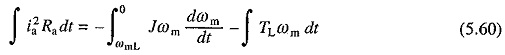
It has been assumed that prior to braking, motor was operating in steady state against a passive load torque TL at a speed ωmL. On integration Eq. (5.60) yields
![]()
This equation indicates that the load absorbs a part of stored kinetic energy and the rest is dissipated as copper loss.
For plugging, on substitution of —V for V and La = 0, in Eqs. (5.52) and (5.53) the following equation is obtained for the copper loss
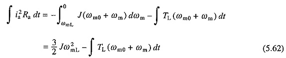
From Eqs. (5.61) and (5.62) the no load copper losses under dynamic braking and plugging will be 1/2 Jω20 and 3/2 Jω20 respectively. Thus, loss during plugging will be three times that during dynamic braking. Since during plugging energy obtained from the kinetic energy of rotating parts is only 1/2 Jω2m0, remainder Jω2m0 is drawn from the supply.
Transient Analysis of Separately Excited Motor with Field Control:
Let the armature voltage be maintained constant. Now
Here Φ is a nonlinear function of if. If saturation is neglected and Φ is assumed to be proportional to if then (5.64) and (5.65) can be written as
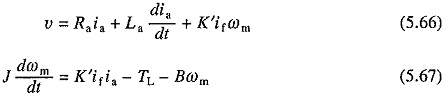
where K′ = KeKΦ.
Because of the terms K′ifωm and K′ifia, which involve product of two variables, (5.66) and (5.67) are nonlinear equations, even though the saturation has been neglected. Thus, this analysis can be carried out using numerical methods of solving non-linear differential equations such as 4th order Runge-Kutta and Predictor-Corrector Methods.
A special case with the field control arises when the armature current is maintained constant. Then the dynamics of motor load system is described by Eq. (5.63) along with the following equation:
![]()
where Ka = KeKΦIa and Ia is the armature current.
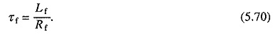
From Eq. (5.68) expression of if and dif/dt can be obtained. Substituting these in Eq. (5.63) and rearranging the’ terms gives

where
The motor can be analysed for its transient response using Eq. (5.69) provided the initial conditions are known. The initial value of ωm will be known from the steady state operating point immediately before the transients and the initial value of dωm/dt is calculated from Eq. (5.68).