Transient Response of RC Circuit:
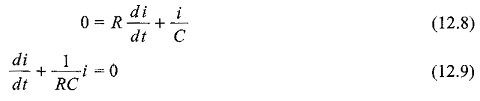
Consider a Transient Response of RC Circuit consisting of resistance and capacitance as shown in Fig. 12.6.
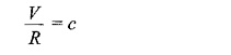
The capacitor in the circuit is initially uncharged, and is in series with a resistor. When the switch S is closed at t = 0, we can determine. the complete solution for the current. Application of the Kirchhoff’s voltage law to the circuit results in the following differential equation.
![]()
By differentiating the above equation, we get
Equation 12.9 is a linear differential equation with only the complementary function. The particular solution for the above equation is zero. The solution for this type of differential equation is
![]()
Here, to find the value of c, we use the initial conditions.
In the Transient Response of RC Circuit shown in Fig. 12.6, switch S is closed at t=0; Since the capacitor never allows sudden changes in voltage, it will act as a short circuit at t=0+. So, the current in the circuit at t=0+ is V/R
![]()
Substituting this current in Eq. 12.10, we get
The current equation becomes
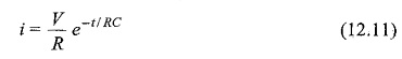
When switch S is closed, the response decays with time as shown in Fig. 12.7.
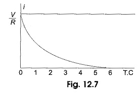
In the solution, the quantity RC is the time constant, and is denoted by τ,
where τ = RC sec
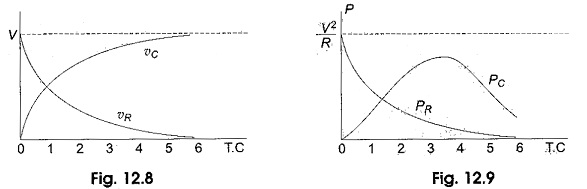
After 5 TC, the curve reaches 99 per cent of its final value. In. Fig. 12.6, we can find out the voltage across each element by using the current equation. Voltage across the resistor is
![]()
Similarly, voltage across the capacitor is
![]()
At t = 0, voltage across capacitor is zero
![]()
The responses are shown in Fig. 12.8.
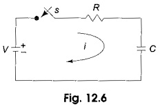
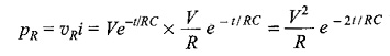
Power in the resistor
Power in the capacitor
![]()
The responses are shown in Fig. 12.9.