Restriking Voltage Transient:
Electrically a power system is an oscillatory network so that it is logical to expect that the interruption of fault current will give rise to a transient, whose frequency depends on the constants of the circuit. It has been pointed out earlier that this transient voltage is referred to as Restriking Voltage Transient, which occurs immediately following arc extinction. The arc voltage across the contacts at this instant is normally quite low, whereas the power frequency voltage in the circuit is at or near its peak value.
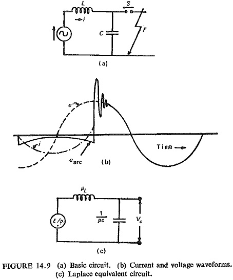
Considering again a simple circuit of Fig. (14.9) in which an inductive source is cleared of a fault condition by the opening of circuit breaker S, arc extinction occurring at an instant of zero current.
The restriking voltage vc, developed across the opened breaker contacts is given in Laplace form by
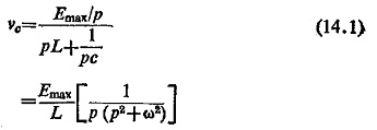
where
ω = 1/√LC
Transforming back into a time function
![]()
The maximum value of restriking voltage vc is 2 Emax and occurs at t = π/ω or equal to π√LC. The oscillatory transient voltage has a frequency of 1/2π√LC Hertz.
Classification of Restriking Transients:
Restriking voltage transients, and consequently their respective circuits can generally be placed under two main headings.
(1) Single Frequency Oscillatory Transients: Conditions are as shown in Fig. (14.9a). The voltage wave form is shown in Fig. (14.9b). When the switch contacts part an arc is formed which normally extinguishes at a current zero, the circuit voltage then being at its peak. This voltage tries to appear across the circuit breaker but is delayed in doing so due to presence of capacitance C, which gets charged and then establishes the voltage across the circuit breaker. However a. transient (restriking) voltage at the natural frequency of the simple L-C series circuit is superimposed on that already existing in the circuit (recovery voltage) as shown in Fig. (14.9b). The natural frequencies are of the order of 1000 to 10,000 Hz.
![]()
(2) Double Frequency Transients: It is quite possible that the circuit breaker S may have L and C parameters on its two sides, as shown in Fig. (14.10). Before clearance the points a and b are at the same potential. After the fault is cleared, i.e. the arc has been extinguished, both the circuits oscillate at their own natural frequencies a composite double frequency transient appears across the circuit breaker S (Fig. (14.10b)).