Transient Response of RLC Circuit:
Consider a Transient Response of RLC Circuit consisting of resistance, inductance and capacitance as shown in Fig. 12.11.
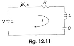
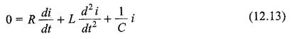
The capacitor and inductor are initially uncharged, and are in series with a resistor. When switch S is closed at t = 0, we can determine the complete solution for the current. Application of Kirchhoff’s voltage law to the Transient Response of RLC Circuit results in the following differential equation.
![]()
By differentiating the above equation, we have
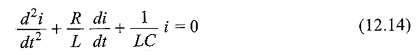
The above equation is a second order linear differential equation, with only complementary function. The, particular solution for the above equation is zero. Characteristic equation for the above differential equation is
![]()
The roots of Eq. 12.15 are
![]()
By assuming
![]()
Here K2 may be positive, negative or zero.
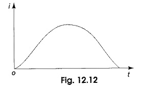
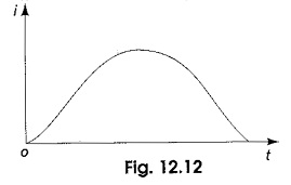
K2 is positive, when (R/2L)2 > 1/LC
The roots are real and unequal, and give the over damped response as shown in Fig. 12.12. Then Eq. 12.14 becomes
![]()
The solution for the above equation is
i = c1 e(K1 + K2)t + c2 e(K1 – K2)t
The current curve for the over-damped case is shown in Fig. 12.12.
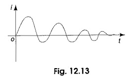
K2 is negative, when (R/2L)2 < 1/LC
The roots are complex conjugate, and give the under-damped response as shown in Fig. 12.13. Then Eq. 12.14 becomes
![]()
The solution for the above equation is
![]()
The current curve for the under-damped case is shown in Fig. 12.13.
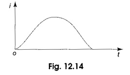
K2 is zero, when (R/2L)2 = 1/LC
The roots are equal, and give the critically damped response as shown in Fig. 12.14. Then Eq. 12.14 becomes
![]()
The solution for the above equation is
![]()
The current curve for the critically damped case is shown in Fig. 12.14.