What is Comparator in Electronics? – Classification and Applications
A circuit used to mark the instant when an arbitrary waveform attains some particular reference level is called a comparator. The clipping circuits can also be used to perform the operation of comparison. In this case the circuits become elements of a comparison system. The only difference between the two is that, in a clipping circuit, part of the signal is required to be reproduced without any distortion, whereas in a comparator in electronics circuit we have no interest in reproducing any part of the signal waveform.
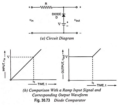
A simple diode comparator circuit is shown in Fig. 30.73 (a). The diode D remains forward biased and, therefore, ‘on’ till the input voltage vin is less than the battery voltage V and the output remains constant at V. As soon as the vin exceeds the V the diode becomes reverse biased and, therefore, switches off and the output voltage vout becomes equal to input voltage vin. The break point is that point when the input voltage vin becomes equal to battery voltage V, also called the reference voltage, at time instant t = t1. Thus the circuit may be used to mark the point at which the input voltage attains the reference level V.
Classification of Comparators:
Comparators are of two types viz., non-regenerative type and regenerative type.
Clipping circuits are examples of non-regenerative comparators. Blocking oscillators, Schmitt trigger circuits are the examples of regenerative comparators in which a positive feedback is employed to have an infinite forward gain (unity loop gain). The Schmitt trigger comparator generates a step input whereas the blocking oscillator comparator generates a pulse output waveform. Operational amplifiers and tunnel diodes may also be used as comparators.
Diode-Differentiator Comparator:
The diode comparator circuit given in Fig. 30.73 is not complete by itself. When the input signal rises past the battery voltage V (reference level), the output voltage will depart from V, this change being applied to the device which is to be actuated. The precise moment at which the device will respond will he governed by its own characteristics. It is convenient to restrain the signal from reaching the actuated device just prior to the moment of comparison. It is also convenient to remove the signal after the comparison operation has been completed. A signal appropriate for this purpose can be generated by double differentiation of the output signal from the circuit given in Fig. 30.74.
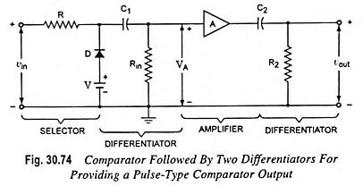
The amplifier is employed to prevent the second differentiator from loading the first one and also serves to increase the amplitude of the output to a convenient level.
Applications of Voltage Comparators:
These are used in electronic systems such as:
- Phase meters.
- Pulse time modulation.
- Accurate measurement of time.
- Timing markers generated from a sinusoidal wave.
- Amplitude distribution analyzers.
- ADC (analog-to-digital converters).
- Conversion of sinusoidal waveform into square waveform.