Phase Comparator Circuit:
Phase Comparator Circuit technique is the most widely used for all practical directional, distance, differential and carrier relays. If the two input signals are S1 and S2 the output occurs when the inputs have a phase relationship lying within specified limits.
Both inputs must exist for an output to occur; ideally, operation is independent of their magnitudes, and is dependent only on their phase relationship.
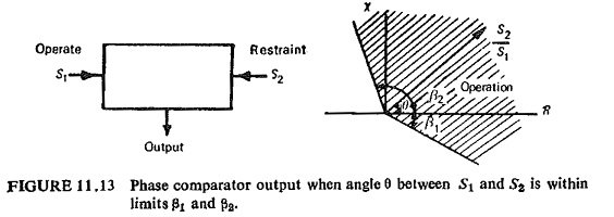
Fig. (11.13) illustrates the Phase Comparator Circuit in its simple form. The function as defined by the boundary of marginal operation is represented by two straight lines from the origin of the complex plane.
The condition of operation can be put mathematically as
![]()
where θ is the angle by which S2 leads S1. If β1=β2=90° the comparator is known as cosine comparator and if β1=0 and β2=180° it is a sine comparator.
Static Phase Comparator Circuits may be of the following types:
- Vector product comparator.
- Coincidence type phase comparator.
Amongst the vector product comparators are the Hall effect phase comparator and the magneto-resistivity phase comparator.