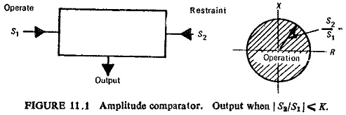
Static Amplitude Comparator:
If the two input signals are S1 and S2 the amplitude comparator gives positive (yes) output only if S2/S1 ≤ K (Fig. (11.1)), S1 is the operating quantity and S2 is the restraining quantity. Ideally, the comparison of the two input signals is independent of their level and their phase relationship. The function is represented by a circle in the complex plane, with its centre at the origin: this defines the boundary of the marginal operation. Static Amplitude Comparator may be of the following types:
-
Integrating comparators,
-
Instantaneous comparators, and
-
Sampling comparators.
Integrating Comparators:
It is possible to arrange rectifier bridge networks as amplitude comparators. Rectifier bridge comparator can either be of circulating current type or opposed voltage type.
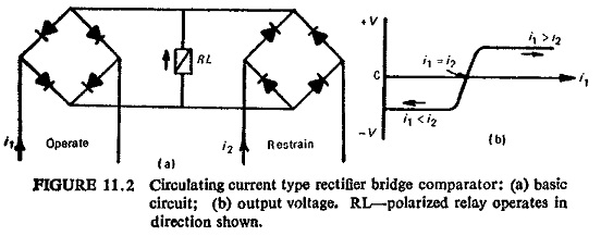
Basic circuit for the circulating current type of Static Amplitude Comparator is shown in Fig. (11.2). The polarized relay operates when S1>S2, where S1=K1i1 and S2=K2i2. This arrangement provides a sensitive relay whose voltage may be ideally represented by Fig. (11.2b). The relay voltage will never exceed twice the forward voltage drop of the rectifiers, and typically will be of the order of 1 volt.
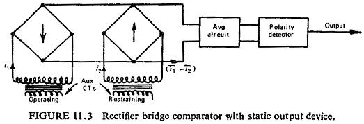
Instead of the polarized relay a static integrator can be used consisting of an averaging circuit and the polarity detector circuit as shown in Fig. (11.3). The two currents i1 and i2 are rectified and their difference (i1 – i2) is averaged. The output is obtained only if the averaged value is positive.
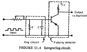
An integrator circuit is shown in Fig. (11.4). The tripping occurs when the capacitor voltage reaches the setting value of the level detector and triggers a thyristor.
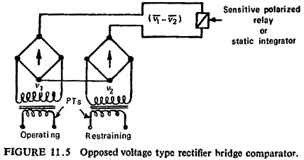
The opposed voltage type comparator shown in Fig. (11.5) works with voltage input signals derived from PTs. The operation in this case depends on the average of the difference of the rectified voltages (v1-v2). In this case the limiting action is the wrong way, as the rectifiers have higher resistance at lower voltages. Also the rectifiers are not protected at higher currents
Instantaneous Comparators:
Instantaneous or direct amplitude comparators can be of two types: averaging type and phase splitting type.
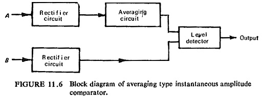
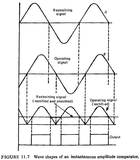
In the averaging type instantaneous amplitude comparator the restraining signal is rectified and smoothed completely in order to provide a level of restraint. This is then compared with the peak value of the operating signal, which may or may not be rectified, but is not smoothed. The tripping signal is provided if the operating signal exceeds the level of restraint. The block schematic diagram is shown in Fig. (11.6). The wave shapes are shown in Fig. (11.7).
Since the above method involves smoothing the operation is slow. A faster method is phase splitting before rectification as shown in Fig, (11.8).
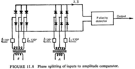
Here the input is split into six components 60° apart, so that, it is smoothed within 5%. The averaging circuit can be eliminated. The operating time here is determined by the time constant of the slowest arm of the phase-splitting circuit and by the speed of the output device.
Sampling Comparators:
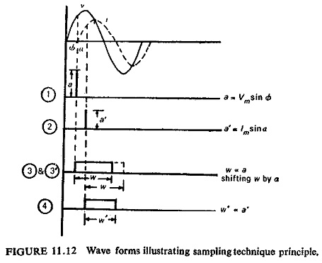
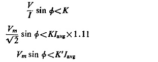
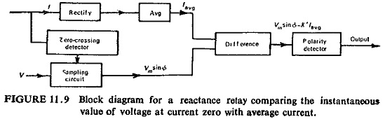
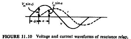
Sometimes it is convenient to get the required characteristics by comparing the magnitude of one input signal at a certain point on its wave against the rectified and smoothed value of the second signal. Reactance characteristic is one such case where the instantaneous value of the voltage at the moment of current zero is compared against the rectified and smoothed value of current. If current I lags behind voltage V by an angle Φ then the value of voltage at current zero is Vm sin Φ.
The reactance relay operates for X < K, i.e.
![]()
The block schematic diagram is shown in Fig. (11.9).
It is also possible to compare the instantaneous magnitude of one signal at a certain moment with the instantaneous magnitude of the second signal at that very moment or at certain other moment. It simply means that one or both signals can be sampled.
For the same reactance relay of the previous case, for operation, we have
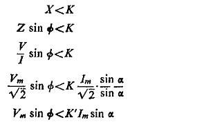
Figure (11.10) shows the voltage and current waveforms.
Comparison Of two instantaneous magnitudes here is made by converting the magnitudes into proportional pulse widths and then comparing with the help of an AND gate. If the two samples are taken at different instants, the pulse width representing the one taken first in time sequence is delayed by the time difference between the two sampling instants, before feeding to the AND gate. The scheme is represented in block diagram in Fig. (11.11), and Fig. (11.12) shows the wave forms.
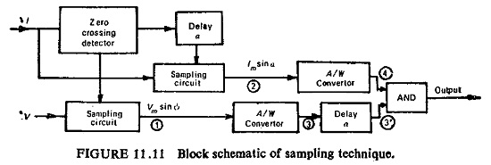
By using sampling techniques we can dispense with the phase shifting and mixing circuits. The elimination of phase shifting and mixing facilities requires a greater degree of sophistication in the relay circuitry but achieves a saving in both space and cost. The measuring circuits are isolated from the transformer secondaries, except during the 50µs sampling period in each half cycle, and the possibility of maloperation due to spikes on the input wave forms is remote.