Extensions of Single Sideband Amplitude Modulation:
The Extensions of Single Sideband Amplitude Modulation is namely,
Forms of Amplitude Modulation:
This section on amplitude modulation defines, describes and lists the main applications of the various forms of AM used for telephony and TV, particularly the various forms of Single Sideband Amplitude Modulation. The International Telecommunications Union (I.T.U.) Radio Regulations also define and describe all forms of emission, however modulated.
A3E (previously A3) Double sideband, full carrier. As already discussed, this is “standard” AM, used for broadcasting and by now for very little else.
R3E (previously A3A) Single-sideband, reduced carrier. This is a pilot carrier system. An attenuated carrier is reinserted into the Single Sideband Amplitude Modulation signal, to facilitate receiver tuning and demodulation. Except for so-called maritime mobile distress frequencies (also known as SOLAS – Safety of Life at Sea), especially 2182 kHz, it is being steadily replaced by J3E, on a worldwide basis.
H3E (previously A3H) Single-sideband, full carrier. This could be used as a compatible AM broadcasting system, with A3E receivers. Distortion not exceeding 5 percent is claimed for H3E transmissions received by an A3E receiver.
J3E (previously A3J) Single-sideband, suppressed-carrier. This is the system so far referred to as “SSB,” in which the carrier is suppressed by at least 45 dB in the transmitter. It was at first slow to take off, because of the high receiver stabilities required. However, with the advent of acceptable synthesizer-driven receivers, it swiftly became the standard form of Single Sideband Amplitude Modulation for radio communications.
B8E (previously A3B) Two independent sidebands, with a carrier that is most commonly attenuated or suppressed. This form of modulation is also known as independent-sideband emission (ISB) and is treated fully in Section 4-4.3. It is used for HF point-to-point radiotelephony, in which more than one channel is required.
C3F (previously A5C) Vestigial sideband (used for television video transmissions). A system in which a vestige, i.e., a trace, of the unwanted sideband is transmitted, usually with a full carrier. This system is treated in Section 4-4.4. It is used for video transmissions in all the world’s various TV systems to conserve bandwidth.
Lincompex This is an acronym which stands for “linked compressor and expander.” It is basically a system in which all audio frequencies above 2.7 kHz are filtered’out to allow for the presence of a control tone at 2.9 kHz with a bandwidth of 120 Hz. Lincompex may be used with any form of AM but is most common with B8E, R3E, and J3E. Before transmission, the signal is passed through an amplitude limiter and a compressor, so that the amplitude of the transmitter output remains virtually constant. This means that there can also be an amplitude limiter in the receiver, similar to the amplitude limiter in an FM receiver (see also Section 5-2), to minimize the effects of noise and fading (see Section 8-2.2). Amplitude variations due to spurious effects will be largely removed, and the received signal will be much better than is usual in HF.
The control tone is frequency-modulated with a signal derived from the transmitter compressor. After reception and demodulation, this signal is applied to the receiver expander, which ensures that the signal out of the receiver is expanded just as it was compressed in the transmitter. The compressor and expander have been linked, and normal signal amplitude variations have been reproduced acceptably. This system is quite popular for commercial HF radiotelephony, as a cheaper alternative to satellite communications on “thin” routes, such as Australia—Antarctica. The quality can be almost as good as that of satellite or undersea cable communications.
Carrier Reinsertion—Pilot-Carrier Systems:
As can be appreciated, J3E requires excellent frequency stability on the part of both transmitter and receiver, because any frequency shift, anywhere along the chain of events through which the information must pass, will cause an equal frequency shift to the received signals. Imagine a 40-Hz frequency shift in a system through which three signals are being transmitted at 200, 400 and 800 Hz. Not only will they all be shifted in frequency to 160, 360 and 760 Hz, respectively, but their relation to one another will also stop being harmonic. The result is that good-quality music is obviously difficult to transmit via J3E. Speech will also be impaired (although it suffers less than music) unless long-term stabilities of the order of 1 part in 107 (or better) are attained.
Such frequency stability has been available from good-quality temperature-stabilized crystal oscillators for many years. That is fine for fixed-frequency transmitters, but receivers are a different proposition altogether, since they must be tunable. Until the advent of frequency synthesizers of less-than-monstrous bulk it was, in fact, simply not possible to produce receiver variable-frequency oscillators stable enough for J3E. The technique that was used to solve this problem, and which is still widely used, is ‘to transmit a pilot carrier with the wanted sideband. The block diagram of such a transmitter is very similar to those already shown, with the one difference that an attenuated carrier signal is added to the transmission after the unwanted sideband has been removed. The technique of carrier reinsertion for a filter system is illustrated in Figure 4-8.
The carrier is normally reinserted at a level of 16 or 26 dB below the value it would have had if it had not been suppressed in the first place, and it provides a reference signal to help demodulation in the receiver. The receiver can then use automatic frequency control (AFC) similar to that described in Section 5-3.3. This topic is further described in Section 6-5.2.
Since the frequency stability obtainable over long-term periods with R3E is of the order of 1 part in 107, such systems are widely employed. They are particularly found in transmarine point-to-point radiotelephony and in maritime mobile communications, especially at the distress frequencies. For high-density traffic, short- or long-haul, different Single Sideband Amplitude Modulation techniques are employed. They are known as frequency- or time-division multiplex and are treated in Chapters 13 through 15.
Independent Sideband (ISB) Systems:
As mentioned in the preceding section, multiplex techniques are used for high-density point-to-point communications. For low- or medium-density traffic, ISB transmission is often employed. The growth of modern communications on many routes has been from a single HF channel, through a four-channel ISB system (with or without Lincompex) to satellite or submarine cable communications.
As shown in the block diagram of Figure 4-8, ISB essentially consists of R3E with two Single Sideband Amplitude Modulation channels added to form two sidebands around the reduced carrier. Each sideband is quite independent of the other. It can simultaneously convey a totally different transmission, to the extent that the upper sideband could be used for telephony while the lower sideband carries telegraphy.
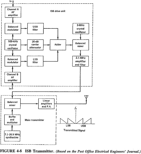
Each 6-kHz channel is fed to its own balanced modulator, each balanced modulator also receiving the output of the 100-kHz crystal oscillator. The carrier is suppressed (by 45 dB or more) in the balanced modulator and the following filter, the main function of the filter still being the suppression of the unwanted sideband, as in all other Single Sideband Amplitude Modulation systems. The difference here is that while one filter suppresses the lower sideband, the other suppresses the upper sideband. Both outputs are then combined in the adder with the —26-dB carrier, so that a low-frequency ISB signal exists at this point, with a pilot carrier also present. Through mixing with the output of another crystal oscillator, the frequency is then raised to the standard value of 3.1 MHz. Note the use of balanced mixers, to permit easier removal of unwanted frequencies by the output filter.
The signal now leaves the drive unit and enters the main transmitter. Its frequency is raised yet again, through mixing with the output of another crystal oscillator, or frequency synthesizer. This is done because the frequency range for such transmissions lies in the HF band, from 3 to 30 MHz. The resulting RF ISB signal is then amplified by linear amplifiers, as might be expected, until it reaches the ultimate level, at which point it is fed to a fairly directional antenna for transmission. The typical power level at this point is generally between 10 and 60 kW peak.
Since each sideband has a width of 6 kHz, it can carry two 3-kHz voice circuits, so that a total of four conversations may be transmitted simultaneously. One set of audio signals in each 6-kHz slot will be translated up by 3 kHz, so as to occupy the range of 3.3 to 5.8 kHz. One or more of the 3-kHz bands may be filled with 15 or more telegraph channels, with the use of multiplexing (see also Section 13-3). It is not altogether advisable to mix telephone and telegraph channels in the one sideband, since “key clicks” may be heard in the voice circuit. Such hybrid arrangements are sometimes unavoidable, however, since demand almost invariably tries to outstrip existing facilities.
Demodulation of ISB in the receiver follows a path similar to that of the Single Sideband Amplitude Modulation process and is covered in Section 6-5.2.
Vestigial Sideband Transmission:
It has been stressed in this chapter that the major advantage of single sideband is the bandwidth saving that accrues from its use, although the power saving cannot be ignored. As we will see in Chapter 6, some demodulation complications arise from the use of J3E, as opposed to AM systems in which a carrier is sent. The greater the bandwidth occupied by a signal, the greater is the spectrum space that can be saved by sending one sideband instead of both. Finally, it was seen in Chapter 3 that, the more information that must be sent in a given time, i.e., per second, the larger the bandwidth required to send it.
We may now turn to the question of transmitting the video signals required for the proper reception of television, noting that the bandwidth occupied by such signals is at least 4 MHz. Bearing in mind filter characteristics, a transmitted bandwidth of
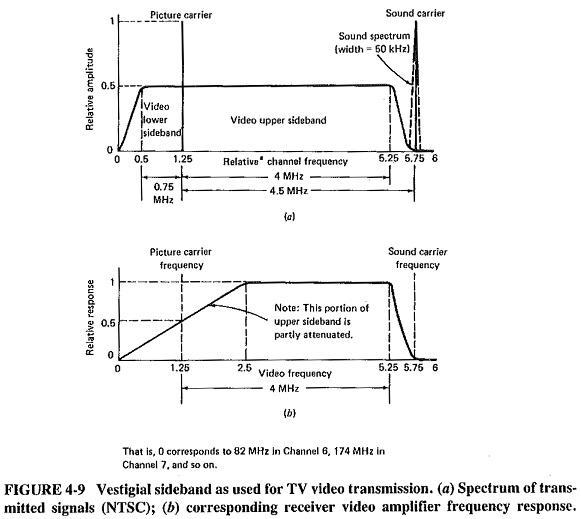
9 MHz would be the minimum requirement if A3E video transmissions were used (this is not practical). The use of some form of Single Sideband Amplitude Modulation is clearly indicated here to ensure spectrum conservation. So as to simplify video demodulation in the receiver, the carrier is, in practice, sent undiminished. Because the phase response of filters, near the edges of the flat bandpass, would have a harmful effect on the received video signals in a TV receiver, a portion of the unwanted (lower) sideband must also be transmitted. The result is vestigial sideband transmission, or C3F, as shown in Figure 4-9a. Please
note that the frequencies shown there, like the ones used in text, refer strictly only to the NTSC TV system in use in the United States, Canada and Japan. The principles are the same, but the frequencies are somewhat different in the PAL TV system used in Europe, Australia and elsewhere, and again different in the French SECAM system. By sending the first 1.25 MHz of the lower sideband (the first 0.75 MHz of it undiminished), it is possible to make sure that the lowest frequencies in the wanted upper sideband are not distorted in phase by the vestigial-sideband filter. Because only the first 1.25 MHz of the lower sideband is transmitted, 3 MHz of spectrum is saved for every TV channel. Since the total bandwidth requirement of a teleyision channel is now 6 MHz instead of 9 MHz, clearly a great saving has been made, and more channels consequently can be accommodated.
To complete the illustration, Figure 4-9a shows the location, in frequency, of the frequency-modulated sound transmissions that accompany the video. It should be noted that these transmissions have nothing to do with the fact that the modulation system for video is C3F, and would have been there regardless of the video Single Sideband Amplitude Modulation system. All these signals occupy frequencies near the video transmissions simply because sound is required with the pictures, and it would not be very practical to have a completely separate receiver for the sound, operating at some frequency remote from the video transmitted frequencies.
Figure 4-9b shows the video frequency response of the television receiver. Attenuation is purposely provided for the video frequencies from 0 to 1.25 MHz. Extra power is transmitted at these frequencies (since they are sent in both sidebands, whereas the remaining video frequencies are not only in the upper sideband). These frequencies would be unduly emphasized in the video output of the receiver if they were not attenuated appropriately.