Amplitude Modulation Theory:
In Amplitude Modulation Theory, the amplitude of a carrier signal is varied by the modulating voltage, whose frequency is invariably lower than that of the carrier. In practice, the carrier may be high-frequency (HF) while the modulation is audio. Formally, AM is defined as a system of modulation in which the amplitude of the carrier is made proportional to the instantaneous amplitude of the modulating voltage.
Let the carrier voltage and the modulating voltage, νc and νm, respectively, be represented by

Note that phase angle has been ignored in both expressions since it is unchanged by the Amplitude Modulation Theory process. Its inclusion here would merely complicate the proceedings, without affecting the result. However, it will certainly not be possible to ignore phase angle when we deal with frequency and phase modulation.
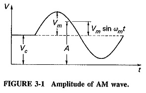
From the definition of AM, you can see that the (maximum) amplitude Vc of the unmodulated carrier will have to be made proportional to the instantaneous modulating voltage Vm sin ωmt when the carrier is amplitude-modulated.
Frequency Spectrum of the AM Wave:
We shall show mathematically that the frequencies present in the AM wave are the carrier frequency and the first pair of sideband frequencies, where a sideband frequency is defined as
![]()
and in the first pair n = 1.
When a carrier is amplitude-modulated, the proportionality constant is made equal to unity, and the instantaneous modulating voltage variations are superimposed onto the carrier amplitude. Thus_when there is temporarily no modulation, the amplitude of the carrier is equal to its unmodulated value. When modulation is present, the amplitude of the carrier is varied by its instantaneous value. The situation is illustrated in Figure 3-1, which shows how the maximum amplitude of the amplitude-modulated voltage is made to vary in accordance with modulating voltage changes. Figure 3-1 also shows that something unusual (distortion) will occur if Vm is greater than Vc (this distortion is a result of overdriving the amplifier stage). This, and the fact that the ratio Vm/Vc often occurs, leads to the definition of the modulation index given in Equation (3-4).
![]()
The modulation index is a number lying between 0 and 1, and it is very often expressed as a percentage and called the percentage modulation.
From Figure 3-1 and Equation (3-4) it is possible to write an equation for the amplitude of the amplitude-modulated voltage. We have
The instantaneous voltage of the resulting amplitude-modulated wave is
![]()
Equation (3-6) may be expanded, by means of the trigonometrical relation sin x sin y = 1/2 [cos (x – y) – cos (x + y)], to give
![]()
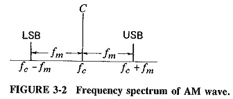
It has thus been shown that the equation of an amplitude-modulated wave contains three terms. The first term is identical to Equation (3-1) and represents the unmodulated carrier. It is apparent that the process of Amplitude Modulation Theory has the effect of adding to the unmodulated wave, rather than changing it. The two additional terms produced are the two sidebands outlined. The frequency of the lower sideband (LSB) is fc – fm, and the frequency of the upper sideband (USB) is fc + fm. The very important conclusion to be made at this stage is that the bandwidth required for Amplitude Modulation Theory is twice the frequency of the modulating signal. In modulation by several sine waves simultaneously, as in the AM broadcasting service, the bandwidth required is twice the highest modulating frequency.
Representation of AM:
Amplitude Modulation Theory may be represented in any of three ways, depending on the point of view. Figure 3-2 shows the frequency spectrum and so illustrates Equation (3-7); AM is shown simply as consisting of three discrete frequencies. Of these, the central frequency, i.e., the carrier, has the highest amplitude, and the other two are disposed symmetrically about it, having amplitudes which are equal to each other, but which can never exceed half the carrier amplitude [see Equation (3-7), and note that m > 1].
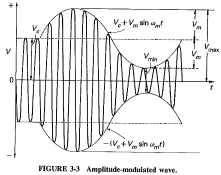
The appearance of the amplitude-modulated wave is of great interest, and it is shown in Figure 3-3 for one cycle of the modulating sine wave. It is derived from Figure 3-1, which showed the amplitude, or what may now be called the top envelope of the AM wave, given by the relation A = Vc + Vm sin ωmt. The maximum negative amplitude, or bottom envelope, is given by -A = -(Vc + Vm sin ωmt). The modulated wave extends between these two limiting envelopes and has a repetition rate equal to the unmodulated carrier frequency.
It will be recalled that Vm = mVc, and it is now possible to use this relation to calculate the index (or percent) of modulation from the waveform of Figure 3-3 as follows:
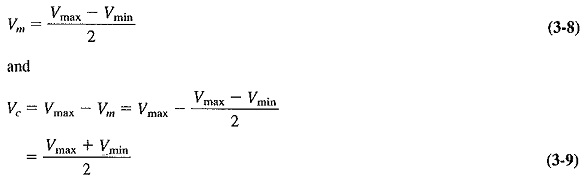
Dividing Equation (3-8) by (3-9), we have
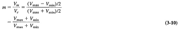
Equation (3-10) is the standard method of evaluating the modulation index when calculating from a waveform such as may be seen on an oscilloscope, i.e., when both the carrier and the modulating voltages are known. It may not be used in any other situation. When only the rms values of the carrier and the modulated voltage or current are known, or when the unmodulated and the modulated output powers are given, it is necessary to understand and use the power relations in the AM wave.
Finally, if the main interest is the instantaneous modulated voltage, the phasor diagrams depicting the three individual components of the AM wave may be drawn.
Power Relations in the AM Wave:
It has been shown that the carrier component of the modulated wave has the same amplitude as the unmodulated carrier. That is, the amplitude of the carrier is unchanged; energy is either added or subtracted. The modulated wave contains extra energy in the two sideband components. Therefore, the modulated wave contains more power than the carrier had before modulation took place. Since the amplitude of the sidebands depends on the modulation index Vm/Vc, it is anticipated that the total power in the modulated wave will depend on the modulation index also. This relation may now be derived.
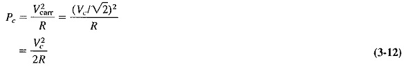
The total power in the modulated wave will be

where all three voltages are (rms) values (√2 converted to peak), and R is the resistance, (e.g., antenna resistance), in which the power is dissipated. The first term of Equation (3-11) is the unmodulated carrier power and is given by
Similarly,
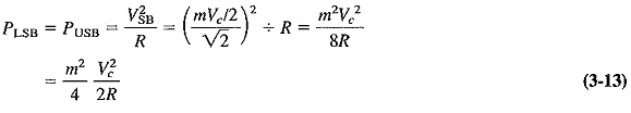
Substituting Equations (3-12) and (3-13) into (3-11), we have
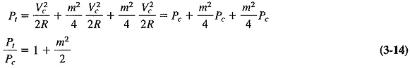
Equation (3-14) relates the total power in the amplitude-modulated wave to the unmodulated carrier power. This is the equation which must be used to determine, among other quantities, the modulation index in instances not covered by Equation (3-10) of the preceding section. The methods of doing this, as well as solutions to other problems, will be shown in exercises to follow.
It is interesting to note from Equation (3-14) that the maximum power in the AM wave is Pt = 1.5Pc when m = 1. This is important, because it is the maximum power that relevant amplifiers must be capable of handling without distortion.
Current calculations:
The situation which very often arises in AM is that the modulated and unmodulated currents are easily measurable, and it is then necessary to calculate the modulation index from them. This occurs when the antenna current of the transmitter is metered, and the problem may be resolved as follows. Let Ic be the unmodulated current and It the total, or modulated, current of an AM transmitter, both being rms values. If R is the resistance in which these currents flow, then

Modulation by several sine waves:
In practice, Amplitude Modulation Theory of a carrier by several sine waves simultaneously is the rule rather than the exception. Accordingly, a way has to be found to calculate the resulting power conditions. The procedure consists of calculating the total modulation index and then substituting it into Equation (3-14), from which the total power may be calculated as before. There are two methods of calculating the total modulation index.
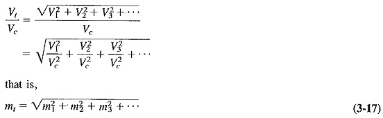
1. Let V1,V2,V3, etc., be the simultaneous modulation voltages. Then the total modulating voltage V, will be equal to the square root of the sum of the squares of the individual voltages; that is,
![]()
Dividing both sides by Vc, we get
2.Equation (3-14) may be rewritten to emphasize tnat the total power in an AM wave consists of carrier power and sideband power. This yields
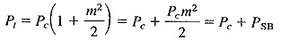
where PSB is the total sideband power and is given by
![]()
If several sine waves simultaneously modulate the carrier, the carrier power will be unaffected, but the total sideband power will now be the sum of the individual sideband powers. We have
![]()
Substitution gives
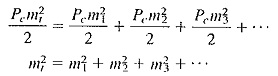
If the square root of both sides is now taken, Equation (3-17) will once again be the result.
It is seen that the two approaches both yield the same result. To calculate the total modulation index, take the square root of the sum of the squares of the individual modulation indices. Note also that this total modulation index must still not exceed unity, or distortion will result as with overmodulation by a single sine wave. Whether Amplitude Modulation Theory is by one or many sine waves, the output of the modulated amplifier will be zero during part of the negative modulating voltage peak if overmodulation is taking place.