What is Current Conveyors (CCs)?
Current conveyors (CCs) were first introduced by Smith and Sedra and have been used in a variety of electronic applications. The CC is a three-port device described by the hybrid equations
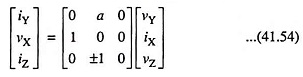
in which symbols for the port variable represent total instantaneous quantities. a = 1 represents the first generation conveyor, denoted as CCI while a = 0 represents the second generation conveyor, denoted as CCII. Also, the plus sign in the equation for iZ in Eq. (41.54) represents the positive current conveyor, denoted as CCI+ or CCII+. In case the minus sign is used, a negative current conveyor, denoted by CCI- or CCII-, is described.
Schematics and ideal symbols for CCIs and CCIIs are given in Fig. 41.16. The current generators driving port Z in the model shown in Fig. 41.16 (b) and 41.16 (d) have two arrows — the downward pointing arrows for positive Current Conveyors, while the upward pointing arrows for negative Current Conveyors. In such models,
current is conveyed from the low-impedance input at port X to the high-impedance at port Z. It is to be noted that the CCI has three dependent sources in its model, while CCII has only two. CCII is more commonly encountered as it is easier to make. When the input to the CCII at port Y is connected to ground, the CCII becomes a gain-of-one current buffer.
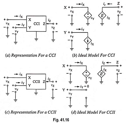
Figure 41.16 gives the ideal models incorporating nullers —CCI model in Fig. 41.17 (a) and CCII model in Fig. 41.17 (b). The simplicity of the model for the CCII makes it attractive for design, and noteworthy point is that, unlike the nuller model for the conventional op-amp, the norator is not required to be grounded. Slightly more complicated model for the CCII+ is shown in Fig. 41.17 (c).
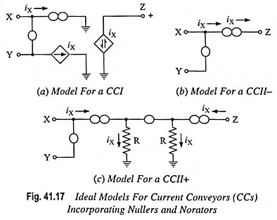
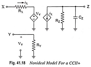
Fig. 41.18 depicts a model for a CCII+ that accounts for some of the imperfections of this operational element. Rx typically ranges from 3 to 50 Ω depending upon which commercial current conveyor is being employed. Ry is typically 2 to 10 MΩ, Rz typically 3 MΩ and CZ may range between 3 and 11 pF. Also, iX and iZ are not exactly equal. That is iZ = (1 + Δ) iX where Δ is a positive number ≪ 1. Typically Δ = 0.005. Finally the, open-loop bandwidth in Hz for a CC with RL = 1 kΩ at port Z may range from 5 to over 20 MHz depending on the current conveyor employed. Similar models apply for the CCII– and for CCIs. Current feedback (CFB) can be had by connecting the output port of a CCII– to a voltage buffer to provide Vout. Then Z for the resulting CFB is RZ/(sCZRZ + 1). The close relationship between CFBs and CCIIs and the fact that the input to the voltage buffer at the output is brought out to a pin are the reasons an AD844CFB can be employed as a CC.
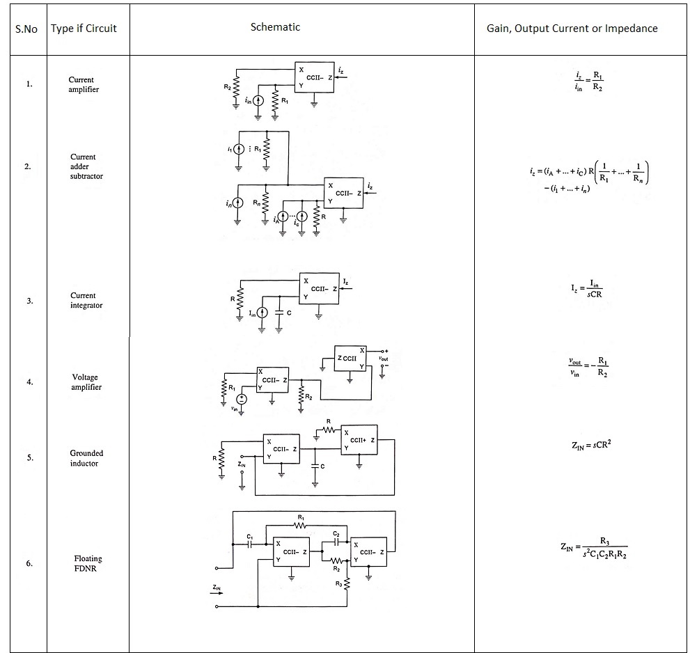
Some of the circuit building blocks based on Current Conveyors have been listed in Table 41.1. In the first four circuits listed, the CCII– can be replaced with a CCII+ yielding an extra minus sign in the result. However, the results for circuit 4 in the table are the same whether a negative or positive CCII is employed for the second CC in the voltage amplifier.
Table 41.1 is shown below
Current Conveyors are particularly suited for current-mode circuits —circuits in which the internal processing of signals is performed on currents rather than voltages. When the voltages at the nodes of a circuit change, the ever-present parasitic capacitances must be charged or discharged, and this is one cause of reduced circuit bandwidth. However, if signals are processed in the form of currents such that voltage amplitudes in the circuit change relatively little, then an improvement in the circuit bandwidth can be had if stray inductance is reduced to minimum.