OTA in Sample and Hold Circuits:
The OTA can be used in sample and hold circuits, as shown in Fig. 41.15.
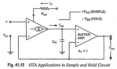
To sample and hold the input signal the control terminal is biased on (= + VCC) and off (= – VEE), so that the holding capacitor CH can hold the signal.
When the circuit is sampling the input signal, the control voltage Vc is high (= + VCC) and the OTA output charges the holding capacitor CH up to value Vin. When the sampled signal is required to hold (i.e., Vc = – VEE) then Ic reduces to zero, and the OTA output virtually behaves as an open circuit so that the holding capacitor holds the sampled input voltage.
How long the holding capacitor stores (holds) the voltage depends upon the output impedance of OTA and input impedance of buffer amplifier.