TV Receiver Synchronizing Circuits:
The task of the TV Receiver Synchronizing Circuits is to process received information, in such a way as to ensure that the vertical and horizontal oscillators in the receiver work at the correct frequencies.
This task is broken down into three specific functions, namely:
- Extraction of sync information from the composite waveform
- Provision of vertical sync pulses (from the transmitted vertical sync pulses)
- Provision of horizontal sync pulses (from the transmitted horizontal, vertical and equalising pulses)
Sync separation (from composite waveform):
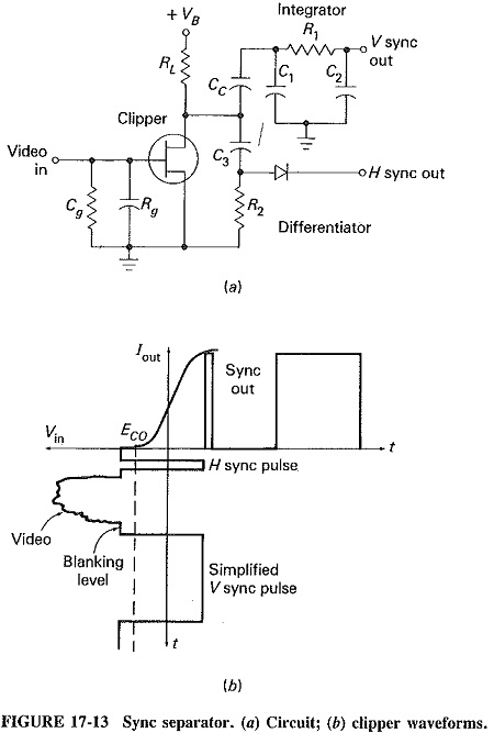
The “clipper” portion of the circuit in Figure 17-13a shows the normal method, of removing the sync information from the composite waveform received. The clipper uses leak-type bias and a low drain supply voltage to perform a function that is rather similar to amplitude limiting. It is seen from the waveforms of Figure 17-13b that video voltage has been applied to an amplifier biased beyond cutoff, so that only the tips of the sync pulses cause output current to flow. It would not be practicable to use fixed bias for the sync clipper, because of possible signal voltage variation at the clipper input. If this happened, the fixed bias could alternate between being too high to pass any sync, or so low that blanking and even video voltages would be present in the output for strong signals: A combination of fixed and leak-type bias is sometimes used.
Horizontal Sync Separation:
The output of the sync clipper is split, as shown in Figure 17-13a, a portion of it going to the combination of C3 and R2. This is a differentiating circuit, whose input and output waveforms are indicated in Figure 17-14. A positive pulse is obtained for each sync pulse leading edge, and a negative pulse for each trailing edge. When the input sync waveform has constant amplitude, no output results from the differentiating circuit. The time constant of the differentiating circuit is chosen to ensure that, by the time a trailing edge arrives, the pulse due to the leading edge has just about decayed. The output does not consist of pulses that are quite as sharp as the simplified ones shown.
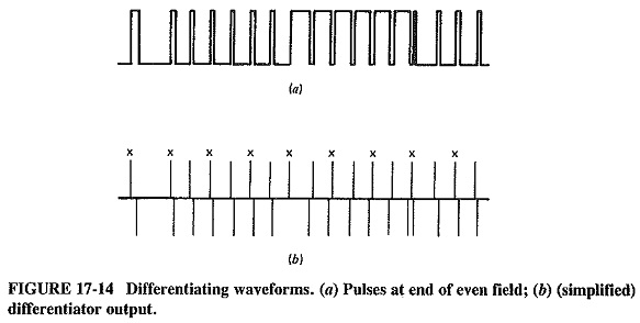
The output of the differentiator, at the junction of C3 and R2 in Figure 17-14, is seen to contain negative pulses as well as the wanted positive ones. These negative-going triggers may be removed with a diode such as the one shown. In practice, the problem is taken care of by the diodes in the horizontal AFC TV Receiver Synchronizing Circuits. Note that not all the positive triggers at the end of a vertical field are actually needed each time. If Figure 17-14 is redrawn to show the situation at the end of an odd field, it will be seen that the pulses not used at the end of the even field will be needed then.
Vertical Sync Separation:
The coupling capacitor Cc in Figure 17-13a is taken to a circuit consisting of C1,R1 and C2, which should be recognised as a standard integrating circuit. Its time constant is made such as to yield the waveforms of Figure 17-15. That is, its time constant is made long compared with the duration of horizontal pulses bin not with respect to the width of the vertical sync pulse. When one considers that the former have widths of about 8 μs, and the width of the latter is just over 190 μs, the task is not seen as a very difficult one. This situation just goes to show how much thought went into the design of the standards themselves. The integrating circuit may be looked upon as a low-pass filter, with a cutoff frequency such that the horizontal sync pulses produce very little output, and the vertical pulses have a frequency that falls into the bandpass of the filter.
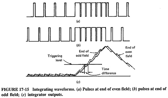
The waveforms of Figure 17-15 explain the operation of the vertical integrator, but they do not represent a real-life situation. They have purposely been drawn to show what would happen if there were no equalizing pulses. As shown by means of the dotted line in Figure 17-15c, without pre-equalizing pulses the charge remaining in the integrating circuit would be greater at the end of the odd field, because the preceding horizontal pulse would have been significantly closer than at the end of an even field.
An oscillator is triggered not because an infinitely thin sync pulse arrives, but when a sync pulse of sufficient width reaches a particular amplitude. This is shown in Figure 17-15c. It is also seen that the integrated pulse at the end of an odd field would reach this level sooner than the pulse produced at the end of an even field. If this were allowed, the odd field would become somewhat shorter (the even field somewhat longer) than the required 262 1/2 lines. A glance at Figure 17-5 reveals that this would have a harmful effect on the interlace mechanism. The lines of one field would no longer be midway between the lines of the other field. The problem could possibly be solved by using an integrating circuit with a much longer time constant, to ensure that it was virtually uncharged by the horizontal pulses. This would have the effect of significantly reducing the integrator output for vertical pulses, so that a vertical sync amplifier would have to be used.
In a broadcasting situation, there are always thousands of receivers for every transmitter. It is much more efficient to cure a potential problem in one transmitter than in thousands of receivers. This is achieved here by transmitting pre-equalizing pulses. Because they are transmitted, the appearance of the pulse train immediately preceding the vertical pulse is now the same at the end of either field, and the resulting output is the same in both cases. Prior to the pre-equalizing pulses there is still an imbalance at the end of the two fields. This is so far upstream that any charge due to this imbalance is dissipated by the time the vertical sync pulse arrives.
The function of the pre-equalizing pulses is seen as the equalisation of charge on the integrating circuit capacitors just before the arrival of the vertical sync pulse. The function of the postequalizing pulses is somewhat less clear. Figure 17-14 shows that the first postequalizing pulse is needed for horizontal synchronisation at the end of an even field, and one supposes that the remaining ones are inserted for symmetry.