Mutual Inductance of Coupled Circuits:
Mutual Inductance of Coupled Circuits – A voltage is induced in a coil when there is a time rate of change of current through it. The inductance parameter L, is defined in terms of the voltage across it and the time rate of change of current through it υ(t) = L di(t)/dt, where υ(t) is the voltage across the coil, I(t) is the current through the coil and L is the inductance of the coil. Strictly speaking, this definition is of self-inductance and this is considered as a circuit element with a pair of terminals. Whereas a circuit element “mutual inductor” does not exist.
Mutual inductance is a property associated with two or more coils or inductors which are in close proximity and the presence of common magnetic flux which links the coils. A transformer is such a device whose operation is based on mutual inductance.
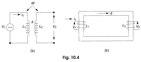
Let us consider two coils, L1 and L2 as shown in Fig. 10.4(a), which are sufficiently close together, so that the flux produced by i1 in coil L1 also link coil L2. We assume that the coils do not move with respect to one another, and the medium in which the flux is established has a constant permeability. The two coils may be also arranged on a common magnetic core, as shown in Fig. 10.4(b).
The two coils are said to be magnetically coupled, but act as a separate circuits. It is possible to relate the voltage induced in one coil to the time rate of change of current in the other coil. When a voltage υ1 is applied across L1, a current i1 will start flowing in this coil, and produce a flux Φ. This flux also links coil L2. If i1 were to change with respect to time, the flux ‘Φ’ would also change with respect to time. The time-varying flux surrounding the second coil, L2 induces an emf, or voltage, across the terminals of L2; this voltage is proportional to the time rate of change of current flowing through the first coil L1.
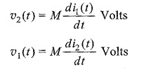
The two coils, or circuits, are said to be inductively coupled, because of this property they are called coupled elements or Mutual Inductance of Coupled Circuits and the induced voltage, or emf is called the voltage/emf of mutual induction and is given by υ2(t) = M1 di1(t)/dt volts, where υ2 is the voltage induced in coil L2 and M1 is the coefficient of proportionality, and is called the coefficient of mutual inductance, or simple mutual inductance.
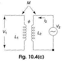
If current i2 is made to pass through coil L2 as shown in Fig. 10.4(c) with coil L1 open, a change of i2 would cause a voltage υ1 in coil L1, given by υ1(t) = M2 di2(t)/dt.
In the above equation, another coefficient of proportionality M2 is involved. Though it appears that two mutual inductances are involved in determining the mutually induced voltages in the two coils, it can be shown from energy considerations that the two coefficients are equal and, therefore, need not be represented by two different letters. Thus M1 = M2 = M.
In general, in a pair of linear time invariant coupled coils or inductors, a non zero current in each of the two coils produces a mutual voltage in each coil due to the flow of current in the other coil. This mutual voltage is present independently of, and in addition to, the voltage due to self induction. Mutual inductance is also measured in Henrys and is positive, but the mutually induced voltage, M di/dt may be either positive or negative, depending on the physical construction of the coil and reference directions. To determine the polarity of the mutually induced voltage (i.e. the sign to be used for the mutual inductance), the dot convention is used.