Resonance Bridge for Measurement of Inductance or Capacitance:
One arm of this Resonance Bridge, shown in Fig. 11.29, consists of a series resonance circuit. The series resonance circuit is formed by Rd, Cd and Ld in series. All the other arms consist of resistors only.
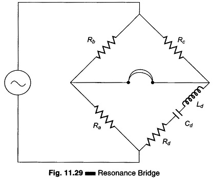
Using the equation for balance, we have Z1Z4 = Z2Z3,
where Z1 = Rb, Z2 = Rc, Z3 = Ra, and Z4 = Rd + jωLd – j/ωCd.
Therefore
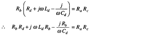
Equating the real and imaginary terms
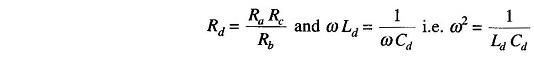
we get

Therefore
Therefore
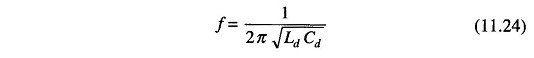
The Resonance Bridge can be used to measure unknown inductances or capacitances. The losses Rd can be determined by keeping a fixed ratio Ra/Rb and using a standard variable resistance to obtain balance. If an inductance is being measured, a standard capacitor is varied until balance is obtained. If a capacitance is being measured, a standard inductor is varied until balance is obtained.The operating frequency of the generator must be known in order to calculate the unknown quantity. Balance is indicated by the minimisation of sound in the headphones.