Series Resonance Circuit:
Series Resonance Circuit – In many electrical circuits, resonance is a very important phenomenon. The study of resonance is very useful, particularly in the area of communications.
For, example, the ability of a radio receiver to select a certain frequency, transmitted by a station and to eliminate frequencies from other stations is based on the principle of resonance.
In a Series RLC Circuit, the current lags behind, or leads the applied voltage depending upon the values of XL and XC . XL causes the total current to lag behind the applied voltage, while XC causes the total current to lead the applied voltage. When XL > XC, the circuit is predominantly inductive, and when XC > XL, the circuit is predominantly capacitive. However, if one of the parameters of the series RLC circuit is varied in such a way that the current in the circuit is in phase with the applied voltage, then the circuit is said to be in resonance.
Consider the series RLC circuit shown in Fig. 8.1.
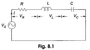
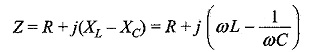
The total impedance for the series RLC circuit is
It is clear from the circuit that the current I = VS/Z
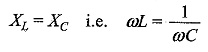
The circuit is said to be in resonance if the current is in phase with the applied voltage. In a series RLC circuit, Series Resonance Circuit occurs when XL = XC. The frequency at which the resonance occurs is called the resonant frequency.
Since XL = XC, the impedance in a series RLC circuit is purely resistive. At the resonant frequency, fr, the voltages across capacitance and inductance are equal in magnitude. Since they are 180° out of phase with each other, they cancel each other and, hence zero voltage appears across the LC combination.
At resonance
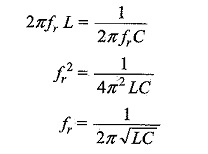
Solving for resonant frequency, we get
In a series RLC circuit, resonance may be produced by varying the frequency, keeping L and C constant; otherwise, resonance may be produced by varying either L or C for a fixed frequency.