Series Circuit:
Series Circuit – The impedance diagram is a useful tool for analyzing series ac circuits. Basically we can divide the series circuits as RL, RC and RLC circuits. In the analysis of series ac circuits, one must draw the impedance diagram. Although the impedance diagram usually is not drawn to scale, it does represent a clear picture of the phase relationships.
Series RL Circuit:
If we apply a sinusoidal input to an RL circuit, the current in the circuit and all voltages across the elements are sinusoidal. In the analysis of the RL series circuit, we can find the impedance, current, phase angle and voltage drops. In Fig. 5.10 (a) the resistor voltage (VR) and current (I) are in phase with each other, but lag behind the source voltage (VS). The inductor voltage (VL) leads the source voltage (VS). The phase angle between current and voltage in a pure inductor is always 90°. The amplitudes of voltages and currents in the circuit are completely dependent on the values of elements (i.e. the resistance and inductive reactance). In the circuit shown, the phase angle is somewhere between zero and 90° because of the series combination of resistance with inductive reactance, which depends on the relative values of R and XL.
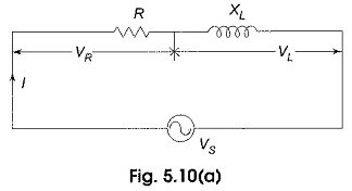
The phase relation between current and voltages in a series RL circuit is shown in Fig. 5.10(b).
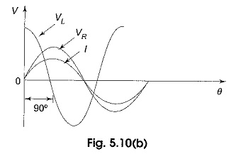
Here VR and I are in phase. The amplitudes are arbitrarily chosen. From Kirchhoff s voltage law, the sum of the voltage drops must equal the applied voltage. Therefore, the source voltage VS is the phasor sum of VR and VL.
![]()
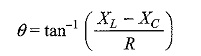
The phase angle between resistor voltage and source voltage is
![]()
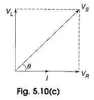
where θ is also the phase angle between the source voltage and the current. The phasor diagram for the series RL circuit that represents the waveforms in Fig. 5.10(c).
Series RC Circuit:
When a sinusoidal voltage is applied to an RC series circuit, the current in the circuit and voltages across each of the elements are sinusoidal. The series RC circuit is shown in Fig. 5.13 (a).
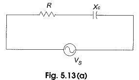
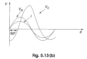
Here the resistor voltage and current are in phase with each other. The capacitor voltage lags behind the source voltage. The phase angle between the current and the capacitor voltage is always 90°. The amplitudes and the phase relations between the voltages and current depend on the ohmic values of the resistance and the capacitive reactance. The circuit is a series combination of both resistance and capacitance; and the phase angle between the applied voltage and the total current is somewhere between zero and 90°, depending on the relative values of the resistance and reactance. In a series RC circuit, the current is the same through the resistor and the capacitor. Thus, the resistor voltage is in phase with the current, and the capacitor voltage lags behind the current by 90° as shown in Fig. 5.13(b).
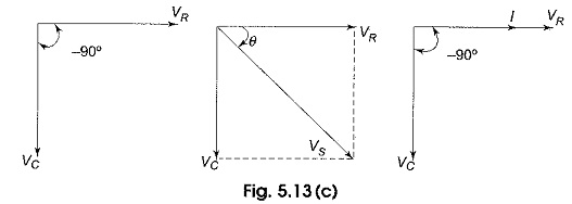
Here, I leads VC by 90°. VR and I are in phase. From Kirchhoff’s voltage law, the sum of the voltage drops must be equal to the applied voltage. Therefore, the source voltage is given by
![]()
The phase angle between the resistor voltage and the source voltage is
![]()
Since the resistor voltage and the current are in phase, θ also represents the phase angle between the source voltage and current. The voltage phasor diagram for the series RC circuit, voltage and current phasor diagrams represented by the waveforms in Fig. 5.13(b) are shown in Fig. 5.13(c).
Series RLC Circuit:
A series RLC circuit is the series combination of resistance, inductance and capacitance. If we observe the impedance diagrams of series RL and series RC circuits as shown in Fig. 5.16(a) and (b), the inductive reactance, XL, is displayed on the + j axis and the capacitive reactance, XC, is displayed on the – j axis. These reactance are 180° apart and tend to cancel each other.
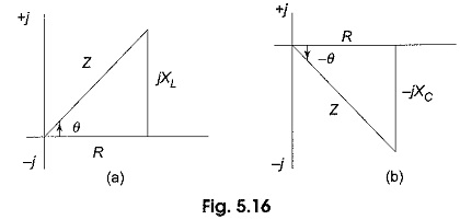
The magnitude and type of reactance in a series RLC circuit is the difference of the two reactance. The impedance for an RLC series circuit is given by
![]()
Similarly, the phase angle for an RLC circuit is