Voltage Series Negative Feedback Amplifier:
In a negative feedback amplifier, a small portion of the output voltage is fed back to the input. When the feedback voltage is applied in series with the signal voltage, the arrangement is Voltage Series Negative Feedback Amplifier. The instantaneous polarity of the feedback voltage is normally opposite to the signal voltage polarity, (they are in series-opposition). So, the feedback voltage is negative with respect to the signal voltage; hence the term negative feedback. 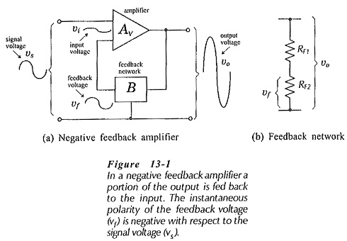
Consider the illustration in Fig. 13-1(a). An amplifier with two input terminals and one output is shown (in triangular representation). The amplifier has a voltage gain (Av), and its output voltage (vo) is applied to a feedback network that reduces vo by a factor (B) to produce a feedback voltage (vf). The feedback network may be as simple as the resistive voltage divider shown in Fig. 13-1(b). At the amplifier input, the instantaneous level of vf is applied negative with respect to vs, so that the amplifier input terminal voltage is,
![]()
Because the amplifier Input voltage is lower than the signal voltage, the output voltage is lower than that produced when negative feedback is not used. This means, of course, that the overall voltage gain (vo/vi) is reduced by negative feedback. However, as will be demonstrated, the stability of the voltage gain is greatly improved with Voltage Series Negative Feedback Amplifier.
Voltage Gain with Negative Feedback Amplifier:
Consider the feedback amplifier illustrated in Fig. 13-2, and recall that vi is amplified to produce vo, and that vo is divided by the feedback network to produce vf. Also, that vf is applied (along with vs) to the amplifier input. It is seen that there is a closed loop from the amplifier input to the output, and then back to the input. Because of this closed loop, the overall voltage gain with negative feedback is termed the closed-loop gain (ACL).
When the feedback network is disconnected, the loop is opened, and the gain without feedback is referred to as the open-loop gain (Av). Alternative symbols sometimes used for the open-loop gain are AOL and Av(OL).
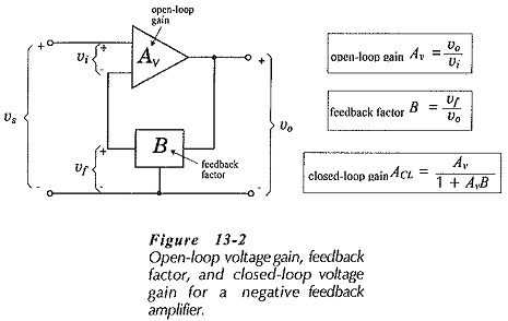
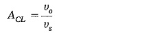
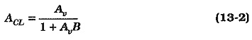
The overall voltage gain (closed-loop gain) of the amplifier in Fig. 13-2 is,
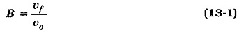
and the feedback factor is,
The input voltage is,
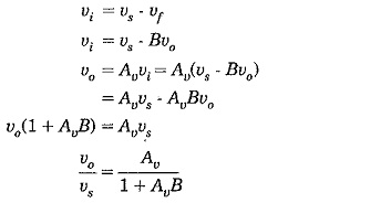
So, the equation for overall voltage gain with negative feedback is,
Analysis of any transistor amplifier not using negative feedback shows that the voltage gain has a wide range, depending on the actual hfe values of the transistors used. Consequently, the open-loop gain of a Voltage Series Negative Feedback Amplifier can vary significantly.
“Series Voltage Negative Feedback Amplifier stabilizes amplifier voltage gain”
Amplifier gain stabilization is the most important advantage of negative feedback amplifiers. Amplifiers that are required to have stable voltage gain are always designed as Voltage Series Negative Feedback Amplifier. Examination of Eq. 13-2 reveals that if AvB >> 1, then
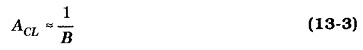
From Eq. 13-3, it is seen that to design a negative feedback amplifier with a particular closed-loop gain, it is only necessary to design the feedback network to give ACL ≈ 1/B. For example, for ACL = 100, B ≈ 1/100. It must be remembered that for Eq. 13-3 to be correct, AvB >> 1, or
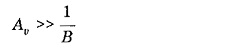
which means that,![]()
Thus, for satisfactory operation of a negative feedback amplifier,
“the open-loop voltage gain must be much greater than the required closed-loop gain”
In general, for ACL to be stable within ±1%, Av should be equal to or greater than 100 ACL.
Effect of Negative Feedback on Input Impedance:
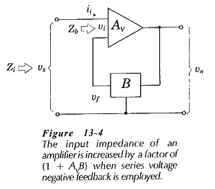
The input impedance of a BJT amplifier without negative feedback is typically the impedance looking into the base of a transistor. If no negative feedback is present in the amplifier in Fig. 13-4, the input impedance is,
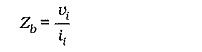
and this gives,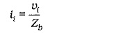
With negative feedback, the input impedance is,
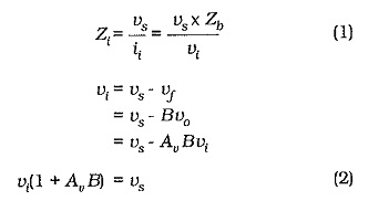
Substituting for vs from Eq. 2 into Eq. 1 gives,
![]()
where Zi is the Negative Feedback on Input Impedance, and Zb is the input impedance without negative feedback. It is seen that
“series voltage feedback increases the input impedance of an amplifier by a factor of (1 + AvB)”
This is the same factor involved in gain reduction.
Input Impedance with Bias Resistors:
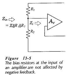
The bias resistors at the input of a transistor circuit (BJT or FET) are not normally affected by series voltage negative feedback, (see Fig. 13-5). This is because the bias resistors are outside the feedback loop. The circuit input resistance in Fig 13-5 is,
![]()
Effect of Negative Feedback on Output Impedance:
To derive an equation for the Effect of Negative Feedback on Output Impedance, refer to Fig. 13-7. This is similar to the circuit of Fig. 13-1, but showing the internal impedance at the amplifier output terminal. The input terminals are short-circuited, so that vf is the only voltage at the amplifier input. The output impedance without feedback is identified as Zc, (the output impedance at a BJT collector terminal, normally equal to 1/hoe).
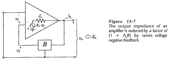
The output voltage (vo) produces the feedback voltage (vf), and this generates a voltage Avvf in series with Zc, as illustrated. Assuming an instantaneous positive polarity for vo, the output current (io) occurs in the direction shown.
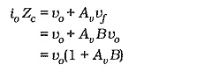
Writing an equation for the voltage drops around the output circuit of the Voltage Series Negative Feedback Amplifier,
![]()
The output impedance of the negative feedback amplifier is,
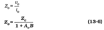
In Eq. 13-6, Zo is the output impedance with negative feedback, and Zc is the output impedance without negative feedback. So,
“series voltage feedback reduces the output impedance of an amplifier by a factor of (1 + AvB)”
This is the same factor involved in the reduction of amplifier gain, and in the increase of the input impedance.
Output Impedance with a Collector Resistor:
The collector resistor in the second stage of a two-stage circuit is not normally affected by Voltage Series Negative Feedback Amplifier, (see Fig. 13-8). This is because (like the case of input bias resistors) the collector resistor is outside the feedback loop.
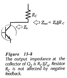
We already know earlier that, for a CE circuit, Zc = 1/hoe, and Zo = RC||(1/hoe). Because 1/hoe is usually much larger than RC, Zo is usually taken as equal to RC when there is no feedback involved. However, with negative feedback, the collector output impedance is much lower than 1/hoe.
From Eq. 13-6,
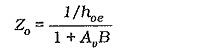
So, the circuit output impedance should be calculated as,
![]()