Negative Resistance Amplifier:
The classical application of the tunnel diode was in microwave oscillators, especially after it was realized that the secret of stable oscillations lay in loosely coupling the diode to its tuned circuit. Other semiconductor devices have subsequently appeared, producing far more microwave power than the tunnel diode ever could. The tunnel diode has been superseded in some of its traditional oscillator applications. It is important to realize that the tunnel diode is a fully fledged active device, like the transistor, so that amplification may be performed with it. It will now be used as a vehicle to introduce Negative Resistance Amplifier in general. These are common at microwaves, and indeed negative-resistance parametric amplifiers have already been met.
Theory of Negative Resistance Amplifier:
It can be shown that a circuit incorporating a Negative Resistance Amplifier is capable of significant power gain. This is obvious, since negative-resistance oscillators are able to oscillate, it is clear that the negative resistance must be making up all the circuit losses. It feeds power into the circuit, which dissipates some and puts out the rest. This is similar to the feedback oscillator situation, in which pa must at least equal unity, and therefore gain certainly exists. The proof for the tunnel diode now follows, but it is really independent of the particular device used to provide the negative resistance.
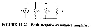
Consider the basic Negative Resistance Amplifier of Figure 12-22. It consists of an input current source is, together with the source conductance gs, connected to a negative conductance – g. Across this the load conductance gL is also connected. The current source and parallel circuit are used for ease of proof. If the frequency is not so high that rs and Ls of the tunnel-diode equivalent circuit must be taken into account, and if the junction capacitance Cj is tuned out, the – g is a suitable representation of the tunnel diode. In the, absence of the diode, the maximum power available from the generator will be when gL= gs, i.e.,
![]()
With the diode present, the load voltage is
![]()
The power delivered to the load is

If the presence of the diode has permitted power gain, the ratio of Equation (12-5) to Equation (12-4) is greater than unity. Then
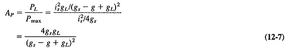
For maximum power transfer , the load and generator conductance are made equal as before. With this new condition we have
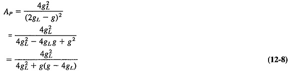
Equation (12-8) can obviously be greater than 1, provided that the second term in its denominator is negative, i.e., provided that 4gL, is greater than g. If this applies, Ap exceeds unity, real power gain is available, and the circuit may be used as an amplifier. Care must be taken to ensure that the denominator of Equation (12-8) is not reduced to zero, which would happen for a value of g such that the last term of Equation (12-8) is equal to – 1. Simple algebra shows that this would occur when
![]()
It is seen that an amplifier containing a Negative Resistance Amplifier is capable not only of power gain but also of infinite gain (and therefore oscillation). This occurs when Equation (12-9) holds, and it gives the lower limit for the value of g, and hence the upper limit for the value of the negative resistance. (Note that the lower limit of the negative resistance is governed by the requirement that 4gL must be greater than g.) We have thus proved that the negative-resistance amplifier is capable of power gain if the Negative Resistance Amplifier has a value between the limits just described. If it strays outside these limits, either Equation (12-8) exceeds unity, and therefore power gain is less than 1, or else it becomes negative, and oscillations take place.
Tunnel Diode Amplifier Theory:
For frequencies below self-resonance, Equation (12-7) must be enlarged to include the junction capacitance of the diode. This capacitance is tuned out in an amplifier, but including it yields a useful result. Therefore

This, in turn, gives a resistive cutoff frequency, or figure of merit, for such a diode, which corresponds to the frequency at which the magnitude of ωCj equals the magnitude of – g. Past this frequency, the negative resistance of the tunnel diode disappears. This frequency is given by
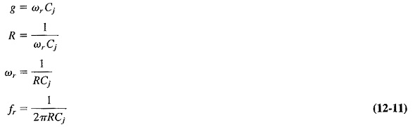
The series diode loss resistance rs has been neglected in this derivation, because it is much smaller than the negative resistance (generally being no more than one-tenth of the Negative Resistance Amplifier) and thus its effect is very small. An alternative interpretation of Equation (12-11) is that it represents the gain-bandwidth product of a tunnel-diode amplifier.