Induction Type Negative Phase Sequence Relay:
This type of induction type negative phase sequence relay has similar construction as that of an induction type overcurrent relay. The difference lies only in the primary winding provided on the central limb of the upper electromagnet which is provided with a central tap resulting into three terminals 1, 2 and 3 of this winding, as shown in Fig. 9.63.
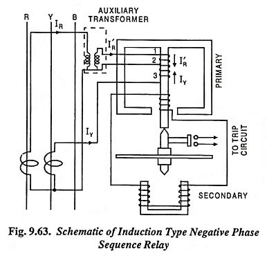
The upper half is energized from phase R through CT and an auxiliary transformer while lower half is energized from phase Y through CT. The auxiliary transformer has special construction (provided with an air gap in its magnetic circuit) in order that the output current of this transformer lags by 120° instead of usual 180° from the input, as illustrated in Fig. 9.64 (a).
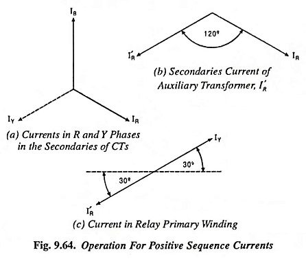
Operation For Positive Sequence Currents:
From Fig. 9.64, it is obvious that the currents I’R and IY flowing through the primary winding of the relay are in opposition, the auxiliary transformer is so arranged that I’R and IY are of equal magnitude. Thus the relay remains inoperative for a balanced system.
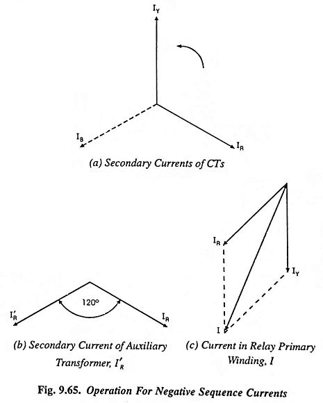
Operation For Negative Sequence Currents:
When there is a fault on the system resulting into a negative phase sequence currents, there is a flow of current I through the primary winding of the relay, as illustrated in Fig. 9.65(c). When the current flowing through the relay primary exceeds the relay setting, the relay operates and trips the circuit.