Negative Phase Sequence Relay:
A negative phase sequence relay (or phase unbalance) is essentially provided for the protection of generators and motors against unbalanced loading that may arise due to phase-to-phase faults.
Essentially such a relay has a filter circuit which is responsive only to the negative sequence components. Since small magnitude overcurrent can cause dangerous conditions, it becomes necessary to have low setting of such relays. No doubt, an earth relay can also provide the desired protection but only in case when there is a fault between any phase and earth. For phase-to-phase faults an earth relay cannot provide necessary protection and hence negative phase sequence relay is required.
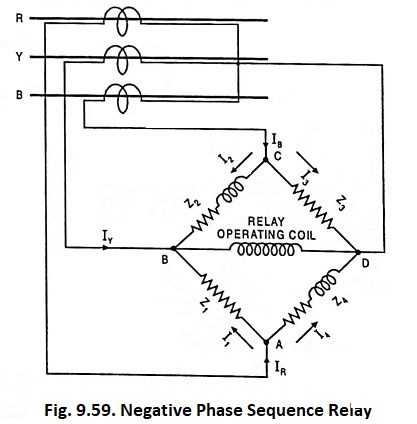
Figure 9.59 illustrates the scheme used for negative phase sequence relay. A network consisting of four impedances Z1, Z2, Z3 and Z4 of equal magnitude connected in a bridge formation is energized from three CTs. A single pole relay having an inverse-time characteristic is connected across the circuit, as illustrated in the figure. Z1 and Z3 are non-inductive resistors while Z2 and Z4 are composed of both resistance and inductance. The values of Z2 and Z4 are so adjusted that currents flowing through them lag behind those in impedances Z3 and Z1 by 60°. The relay is assumed to have negligible impedance. The current from phase R at junction A is equally divided into two branches as I1 and I4 but I4 will lag behind I1 by 60°.
From Fig. 9.60

Similarly the current from phase B divide at junction C into two equal components I3 and I2; I2 lagging behind I3 by 60°.

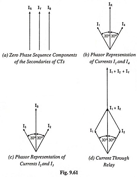
Note that I1 leads IR by 30° while I4 lags behind IR by 30°. Similarly I2 lags behind IB by 30°, whereas I3 leads IB by 30°.
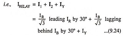
The current through relay operating coil at junction B will be equal to phasor sum of I1, I2 and IY.
Flow of + ve Sequence Currents:
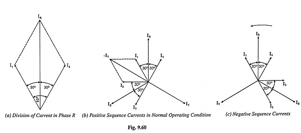
Figure 9.60 (b) represents the phasor diagram when the load is balanced or when there is no negative sequence current. Since the current through the relay is I1 + I2 + IY = 0 because I1 + I2 = -IY
So the relay remains in operative for a balanced system.
Flow of – ve Sequence Currents:
Figure 9.60 (c) represents the phasor diagram for negative sequence currents. It is noted that at junction B current I1 and current I2 are equal but opposite to each other, so they cancel each other and current IY flows through the relay operating coil. Thus the relay operates due to flow of current IY through it. A low setting value well below the normal full-load rating of the machine is provided since comparatively small values of unbalance currents produce a great danger.
Flow of Zero Sequence Currents:
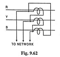
The current at junction B of the relay is represented in phasor diagram [Fig. 9.61 (d)] from which it is observed that the currents I1 and I2 are displaced from each other by 60°, so that the resultant of these currents is in phase with the current in phase Y. Thus a total current of twice the zero sequence current would flow through the relay and would therefore cause its operation.
To make the relay inoperative under the influence of zero sequence current, the CTs are connected in delta as shown in Fig. 9.62 because then no zero sequence current can flow in the network circuit.