Sequence Impedances and Networks of Synchronous Machine:
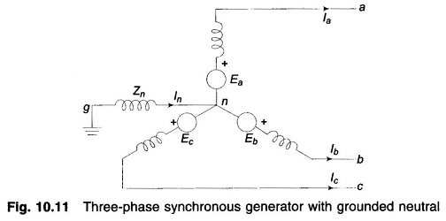
Sequence Impedances and Networks of Synchronous Machine – Figure 10.11 depicts an unloaded synchronous machine (generator or motor) grounded through a reactor (impedance Zn). Ea, Eb and Ec are the induced emfs of the three phases. When a fault (not shown in the figure) takes place at machine terminals, currents Ia, Ib and Ic flow in the lines. Whenever the fault involves ground, current In = Ia + Ib+ Ic flows to neutral from ground via Zn. Unbalanced line currents can be resolved into their symmetrical components Ia1, Ia2 and Ia0. Before we can proceed with fault analysis, we must know the equivalent circuits presented by the machine to the flow of positive, negative and zero sequence currents, respectively. Because of winding symmetry currents of a particular sequence produce voltage drops of that sequence only. Therefore, there is a no coupling between the equivalent circuits of various sequences.
Positive Sequence Network of Synchronous Machine:
Since a synchronous machine is designed with symmetrical windings, it induces emfs of positive sequence only, i.e. no negative or zero sequence voltages are induced in it. When the machine carries positive sequence currents only, this mode of operation is the balanced mode. The armature reaction field caused by positive sequence currents rotates at synchronous speed in the same direction as the rotor, i.e., it is stationary with respect to field excitation. The machine equivalently offers a direct axis reactance whose value reduces from subtransient reactance (X”d) to transient reactance (X′d) and finally to steady state (synchronous) reactance (Xd), as the short circuit transient progresses in time. If armature resistance is assumed negligible, the positive Sequence Impedances and Networks of Synchronous Machine is
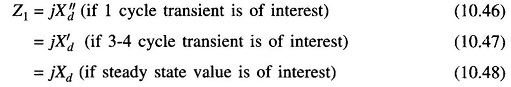
If the machine short circuit takes place from unloaded conditions, the terminal voltage constitutes the positive sequence voltage; on the other hand, if the short circuit occurs from loaded conditions, the voltage behind appropriate reactance (subtransient, transient or synchronous) constitutes the positive sequence voltage.
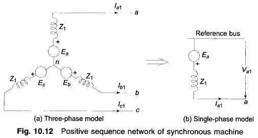
Figure 10.12a shows the three-phase positive sequence network model of a synchronous machine. Zn does not appear in the model as In = 0 for positive sequence currents. Since it is a balanced network it can be represented by the single-phase network model of Fig. 10.12b for purposes of analysis. The reference bus for a positive sequence network is at neutral potential. Further, since no current flows from ground to neutral, the neutral is at ground potential.
With reference to Fig. 10.12b, the positive sequence voltage of terminal a with respect to the reference bus is given by
![]()
Negative Sequence Network of Synchronous Machine:
It has already been said that a synchronous machine has zero negative sequence induced voltages. With the flow of negative sequence currents in the stator a rotating field is created which rotates in the opposite direction to that of the positive sequence field and, therefore, at double synchronous speed with respect to rotor. Currents at double the stator frequency are therefore induced in rotor field and damper winding. In sweeping over the rotor surface, the negative sequence mmf is alternately presented with reluctances of direct and quadrature axes. The negative Sequence Impedances and Networks of Synchronous Machine with consideration given to the damper windings, is often defined as
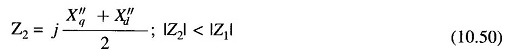
Negative sequence network models of a synchronous machine, on a three-phase and single-phase basis are shown in Figs. 10.13a and b, respectively. The reference bus is of course at neutral potential which is the same as ground potential.
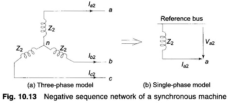
From Fig. 10.13b the negative sequence voltage of terminal a with respect to reference bus is
![]()
Zero Sequence Network of a Synchronous Machine:
We state once again that no zero sequence voltages are induced in a synchronous machine. The flow of zero sequence currents creates three mmfs which are in time phase but are distributed in space phase by 120°. The resultant air gap field caused by zero sequence currents is therefore zero. Hence, the rotor windings present leakage reactance only to the flow of zero sequence currents (Z0g < Z2 < Z1).
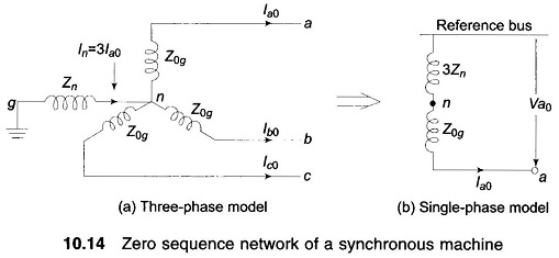
Zero sequence network models on a three- and single-phase basis are shown in Figs. 10.14a and b. In Fig. 10.14a, the current flowing in the impedance Zn between neutral and ground is In = 3Ia0. The zero sequence voltage of terminal a with respect to ground, the reference bus, is therefore
![]()
where Z0g is the zero sequence impedance per phase of the machine.
Since the single-phase zero sequence network of Fig. 10.14b carries only per phase zero sequence current, its total zero sequence impedance must be
![]()
in order for it to have the same voltage from a to reference bus. The reference bus here is, of course, at ground potential.
From Fig. 10.14b zero sequence voltage of point a with respect to the reference bus is
![]()
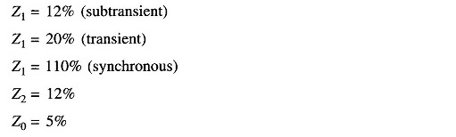
Order of Values of Sequence Impedances of a Synchronous Generator:
Typical values of Sequence Impedances and Networks of Synchronous Machine of a turbo-generator rated 5 MVA, 6.6 kV, 3,000 rpm are: