Sequence control of Converters:
Sequence control of Converters – We have shown that fully controlled converters take lagging reactive power from the mains. This requirement is less in half controlled converters and converters with a freewheeling diode, which however do not provide the process of inversion. In both cases the reactive power requirement increases as the angle of firing is retarded.
It is possible to improve the behaviour of the converter with respect to control reactive power requirement, by the sequential control of two or more converters connected in series; Besides improving the reactive power consumption converters with sequential control can also be used for high voltages at the output.
When several converters are connected in series and controlled one after another, it is called sequence control. The reactive power requirement of the converters in this method is considerably less than the sum of each individually.
1. Series control of 3-phase bridge circuits:
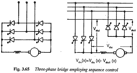
A 3-phase bridge circuit is obtained by a series connection of 3-phase converters. For α = 0 the dc voltage is zero. The thyristors of both the 3-phase converters are controlled simultaneously.
On the other hand, if the 3-phase converters are controlled such that converter I operates as an inverter (Fig. 3.65) and converter II as a rectifier, then when the firing angle of the former is 180° and that of the latter is 0°, the dc voltage Vdiα = 0. The individual converters require zero reactive power.
The converter operates as a rectifier if converter II is uncontrolled (α = 0) and converter I has a transition from an inverter to a rectifier. Only converter I requires reactive power for control. When inverter operation is required, converter I is always operated as an inverter and the firing angle of converter II is retarded from 0°.
In sequence control, the reactive power never exceeds the value of the reactive power, required when a single fully controlled converter is used. When two are used in series, the total reactive power is just half the reactive power required by one converter.
The operation, with respect to reactive power becomes more comfortable if the number of series connected converters increases. The ratio of the reactive power required with sequence control, to the reactive power required with a converter decreases. In view of the resulting complexity, however it is not advisable to use more than two converters in series for sequence control.
Saving is possible only for control reactive power and not for commutation reactive power. As the number of series connected converters increases the commutation reactive power increases, even though there is a saving in control reactive power.
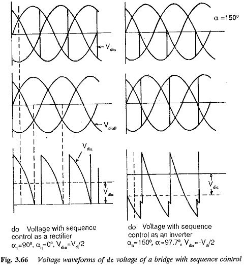
The inverter limit should be given due consideration. Two bridge type converters can also be used for sequence control. The individual bridges may have different initial overlap angles. The dc voltage at the output terminals of 3-phase bridge converters in sequence control is shown in Fig. 3.66a for rectifier operation and Fig. 3.66b for inverter operation.
2.Series connection of two bridge converters with sequence control of both:
This arrangement has a behaviour similar to that of bridge circuit with sequence control of individual converters. It has an advantage of reduced ripple content because of 6-pulse operation.
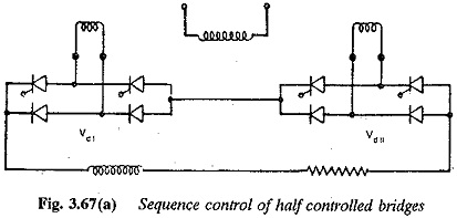
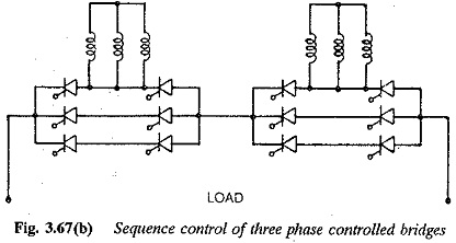
3.Series connection of two bridge converters with sequence control of individual converters:
The arrangement is depicted in Fig. 3.67. The bridges are supplied from a transformer having two secondaries, each supplying one bridge. The reactive power requirement of this arrangement is less than that of a single converter having sequence control in its halves. The converter should be controlled with a definite margin angle of quenching, which decides its inverter limit. It is not worthwhile having more than two converters in series.
Optional free wheeling
Optional free wheeling in the bridges using thyristors is given in Fig 3.68.
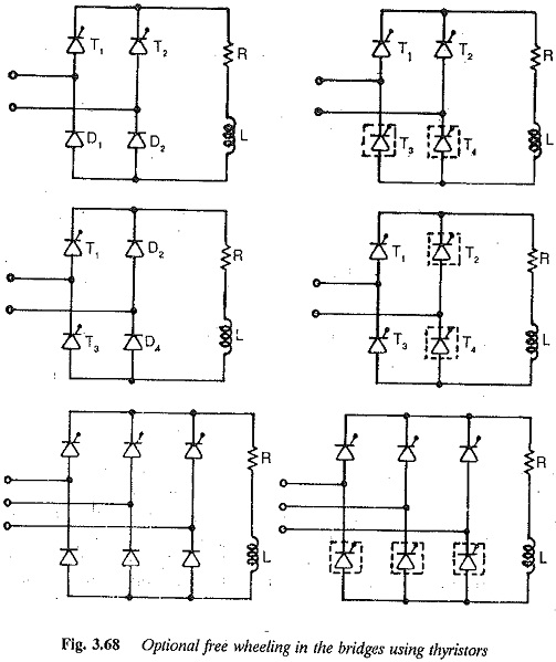
A fully controlled bridge converter has a disadvantage of poor powerfactor at small control ratios. A half controlled bridge converter has a power-factor better than that of a fully controlled one at the same voltage ratio. However, half controlled converters do not possess the capacity of inversion. Thus half controlled converters have limited application as one quadrant ones. It is possible to use a fully controlled bridge circuit as half controlled one by controlling a set of thyristors a diodes by triggering them at their natural firing instant.
When the inversion is required they are operated as thyristors and their firing angles are varied from 90° to 180°. Such a facility is called optional freewheeling. In Fig. 3.68, two quadrant converters are shown with encircled thyristors to provide optional freewheeling. These are controlled as diodes during rectification and as thyristors during inversion. Such a control is possible in converters with freewheeling diodes. Here the diode is replaced by a thyristor which is fired at its natural firing instant for freewheeling action. When the inversion is required the control pulses to the thyristors are blocked and the converter operates as a two quadrant one. Optional freewheeling enables a converter operate in both rectification and inversion modes providing the advantages of free wheeling during rectification. Sequence control discussed in the foregoing is a kind of optional freewheeling providing the advantages during inversion also.