Signal Flow Graph of DC Motor in Electric Drive System:
The Signal Flow Graph of DC Motor in Electric Drive System block diagram representation discussed above is adequate only for simple systems having components with one input and one output. When a system is complex, having many variables, the block diagram reduction may become a very difficult task to perform. In such cases it may be advantageous to have a method using which the overall input-output relationship of the system can be determined without needing to perform a reduction. Such a method is afforded by representing a system by its signal flow graph which has line segments directed in the direction of signal flow. A gain formula is available to determine the input-output relationship between the variables.
As has already been stated, a system can be represented by a set of differential equations. The pictorial representation of these equations by means of nodes which are interconnected by means of directed line segments called branches, is called the signal flow graph of the system. A node of the graph represents a system variable and a branch acts as a single multiplier with the multiplying factor indicated on it. The branches are unidirectional elements allowing Signal Flow Graph of DC Motor in Electric Drive System in the direction of arrow head and are equivalent to blocks in a block diagram.
A multivariable system is represented by state equations of the form
![]()
A Signal Flow Graph of DC Motor in Electric Drive System can be used to represent such a system. The state equations of a separately excited dc motor and its signal flow graph are shown in.
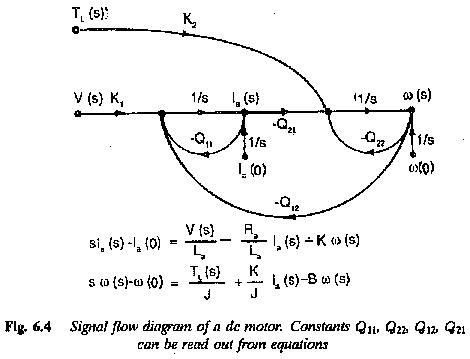
A Signal Flow Graph of DC Motor in Electric Drive System gives the same information given by a block diagram, but has several advantages. Multivariable systems can be represented very easily. Simple flow graphs allow writing down of flick relations by inspection. Time domain solution of the equations of multivariable systems using signal flow is straightforward. There is no need for evaluating the state transition Matrix and convolution integrals. The effect of input is normally taken care of in the formulation of input-output relations of the graph.
Mason’s Gain Formula relating an output variable to an input variable is given by
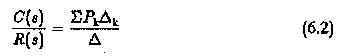
where
Pk is the loop gain defined as the continuous succession of branches in the direction of signal flow, encountering a node only once.
Δk cofactor of the path Pk
Δ determinant of the graph