Node Elimination Technique in Power System:
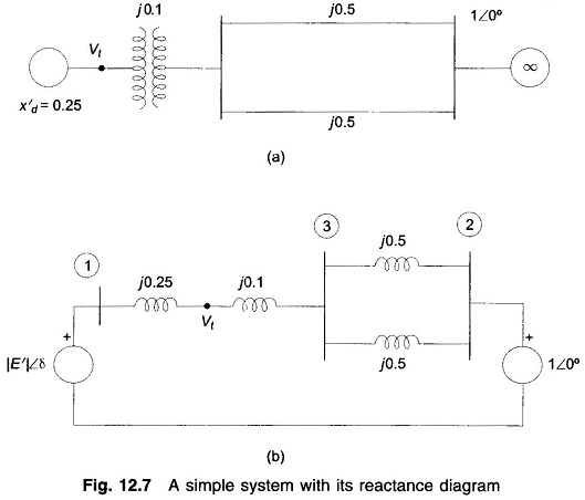
In stability studies, it has been indicated that the buses to be considered are those which are excited by the internal machine voltages (transient emf’s) and not the load buses which are excited by the terminal voltages of the generators. Therefore, in YBUS formulation for the stability study, the load buses must be eliminated. Three methods are available for bus elimination. Node Elimination Technique in Power System are illustrated by the simple system of Fig. 12.7(a) whose reactance diagram is drawn in Fig. 12.7(b). In this simple situation, bus 3 gets easily eliminated by parallel combination of the lines. Thus

Consider now a more complicated case wherein a 3-phase fault occurs at the midpoint of one of the lines in which case the reactance diagram becomes that of Fig. 12.8 (a).
Star Delta Conversion:
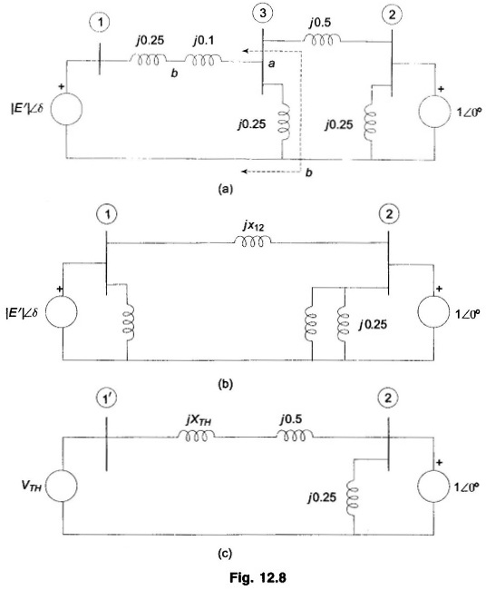
Converting the star at the bus 3 to delta, the network transforms to that of Fig. 12.8(b) wherein

This method for a complex network, however, cannot be mechanized for preparing a computer programme.
Thevenin’s Equivalent:
With reference to Fig. 12.8(a), the Thevenin’s equivalent for the network portion to the left of terminals a b as drawn in Fig. 12.8(c) wherein bus 1 has been modified to 1′.
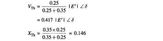
Now
![]()
This method obviously is cumbersome to apply for a network of even small complexity and cannot be computerized.
Node Elimination Technique:
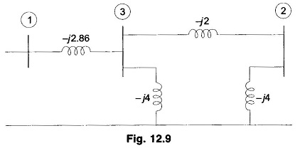
Formulate the bus admittances for the 3-bus system of Fig. 12.8(a). This network is redrawn in Fig. 12.9 wherein instead of reactance branch, admittances are shown. For this Node Elimination Technique in Power System network,

The bus 3 is to be eliminated.
In general for a 3-bus system
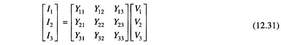
Since no source is connected at the bus 3
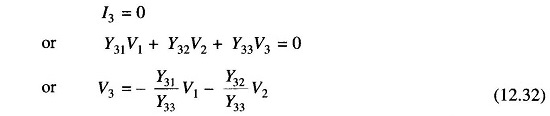
substituting this value of V3 in the remaining two equations of Eq. (12.31), thereby eliminating V3,

In compact form
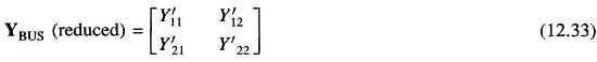
Where
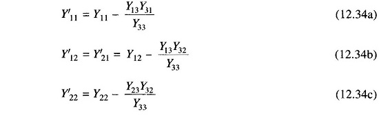
In general, in eliminating node n
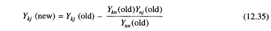
Applying Eq. (12.34) to the example in hand
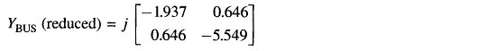
It then follows that
![]()