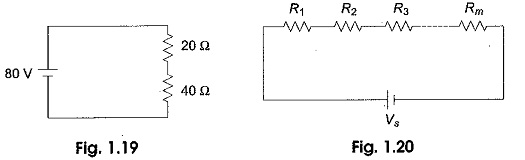
Voltage Divider Circuit Diagram:
The series circuit acts as a Voltage Divider Circuit. Since the same current flows through each resistor, the voltage drops are proportional to the values of resistors. Using this principle, different voltages can be obtained from a single source, called a voltage divider. For example, the voltage across a 40 Ω resistor is twice that of 20 Ω in a series circuit shown in Fig. 1.19.
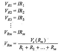
In general, if the circuit consists of a number of series resistors, the total current is given by the total voltage divided by equivalent resistance. This is shown in Voltage Divider Circuit Diagram in Fig. 1.20.
The current in the Voltage Divider Circuit Diagram is given by I=Vs/(R1+R2+…+Rm). The voltage across any resistor is nothing but the current passing through it, multiplied by that particular resistor.
Therefore,
where
- Vm is the voltage across mth resistor,
- Rm is the resistance across which the voltage is to be determined and
- RT is the total series resistance.
From the above equation, we can say that the voltage drop across any resistor, or a combination of resistors, in a series circuit is equal to the ratio of that resistance value to the total resistance, multiplied by the source voltage
Voltage Divider Series Circuit:
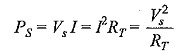
The total power supplied by the source in any series resistive circuit is equal to the sum of the powers in each resistor in series, i.e.
![]()
where
- m is the number of resistors in series,
- PS is the total power supplied by source and
- Pm is the power in the last resistor in series.
The total power in the series circuit is the total voltage applied to a circuit, multiplied by the total current. Expressed mathematically,
where
- Vs is the total voltage applied,
- RT is the total resistance, and
- I is the total current.